This thread has been locked.

If you have a related question, please click the "Ask a related question" button in the top right corner. The newly created question will be automatically linked to this question.

DP83867IR: DP83867irrgzr occasionally fails to connect.

Part Number: DP83867IR
Other Parts Discussed in Thread: AM2732,

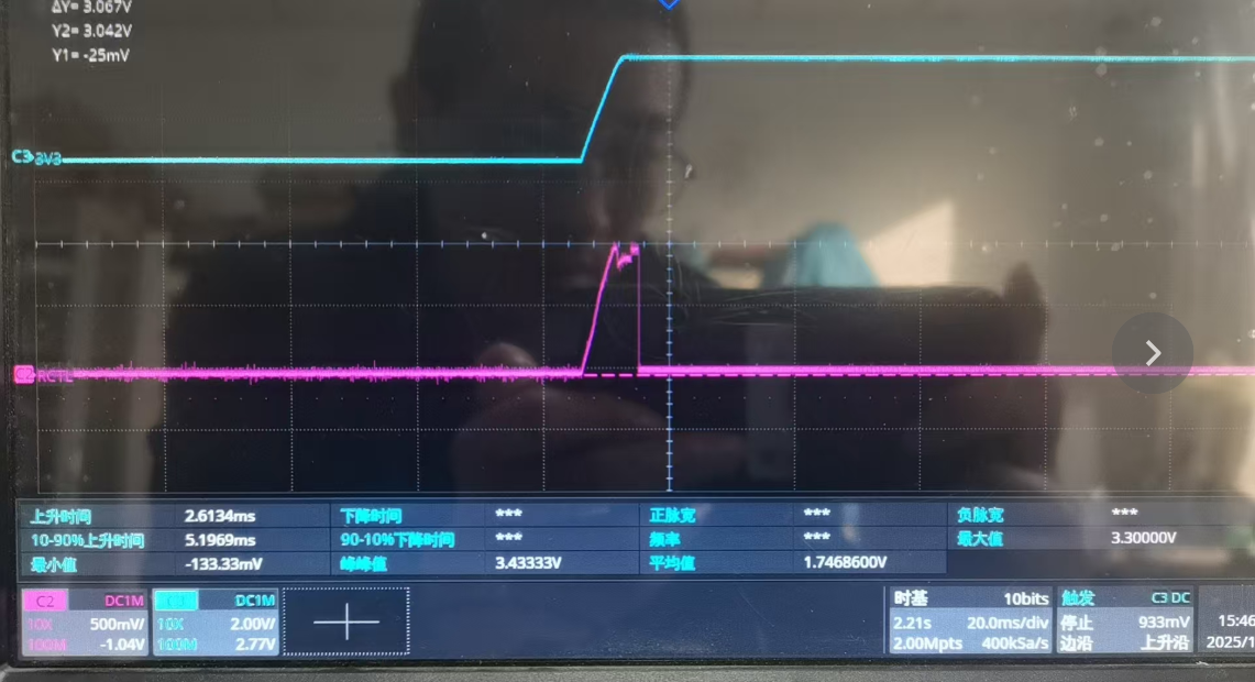
Using AM2732 as the main control and DP83867irrgzr as the phy, during the repeated power-on and power-off process, the PHY occasionally fails to connect. After our investigation, the most likely cause is that RX CTRL did not enter mode3. The pin of RX CTRL is pulled up to 3.3V at 5.76k and down to GND at 2.49k as per the manual. The power-on timing of RX CTRL and 3.3V that we tested did not meet the requirements either, but we were unable to determine the reason why the voltage divider level of RX CTRL could not be maintained. Please help us identify the cause together.

Blue is 3.3v and red is rxctrl

image.png

image.png

  • Hi,

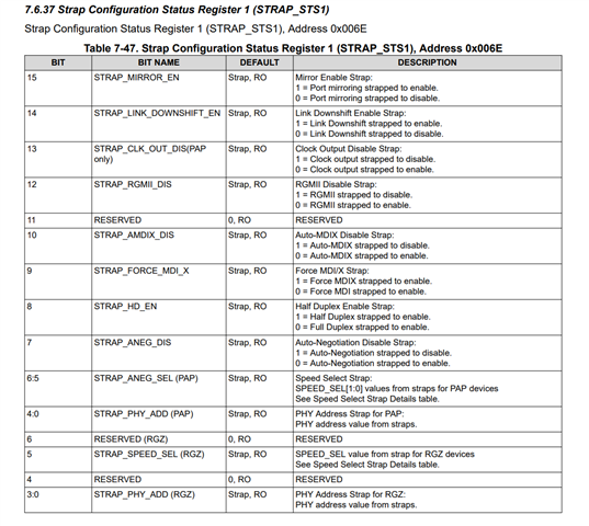
    Can you please read DP83867IR extended register 0x6E between the working and failing case? If RX_CTRL is not strapped correctly, then you should see a difference in bit 7 of register 0x6E?

    What is the VDDIO voltage, is it 3.3V? If the VDDIO is 3.3V, then at Mode 3, you should see a typical voltage of 0.8415V, with Vmin of 0.7425V, and max of 0.9372V. Looking at the scope waveform, it looks like we are violating the voltage threshold requirement. 

    For the 5.76k and 2.49k strapping resistor, are you using 1% tolerance resistor? 

    Does the MAC have internal pullup resistor? If the MAC has internal resistor, then we need to re-calculate the external strapping resistor value, please see this app note for more detail on how to calculate the resistor value. 

    Thanks

    David

  • thanks for support!Now the phy can be found. Now the network is connected to a 100-megabit transformer, but another problem has occurred. The phenomenon is that ping cannot be done, but the phy indicator light indicates that it is already connected. The test network transformer has data for both sending and receiving. The test rxclk does not have a 25M clock, while the test txclk does have a 25M clock. May I ask what caused it?

  • Hi,

    Can you please share your schematic, register dump from 0x00 to 0x1F, and 0x6E?

    RX_CLK provides the recovered receive clock for different mode of operation and it should be 25MHz for 100Mbps. Are you seeing any frequency on the RX_CLK? 

    Thanks

    David

  • There's another issue. If the Doppler cell configuration exceeds 32, it will be incorrect. How can I modify this limit? Can the range be expanded?

  • Hi,

    I am not fully the question here. My understanding on the Doppler cell configuration is a specific region in space and time that is used to measure Doppler shift, how is this related to the DP83867 issue you are having?

    Thanks

    David

  • I should have asked on the ARM forum. Thank you for support. It's already connected.