This thread has been locked.

If you have a related question, please click the "Ask a related question" button in the top right corner. The newly created question will be automatically linked to this question.

TCAN1043A-Q1: Cold start ERR_N pin stuck to LOW issue analysis

Part Number: TCAN1043A-Q1
Other Parts Discussed in Thread: TCAN1043

We are using multi-supliers which means general SW shall cover multiple suppliers. From cold start, other supplier IC behavior was observed that ERR_N was stuck to LOW. But, TI works as expected. So, SW application analysis and IC comparison for cold start are required. 

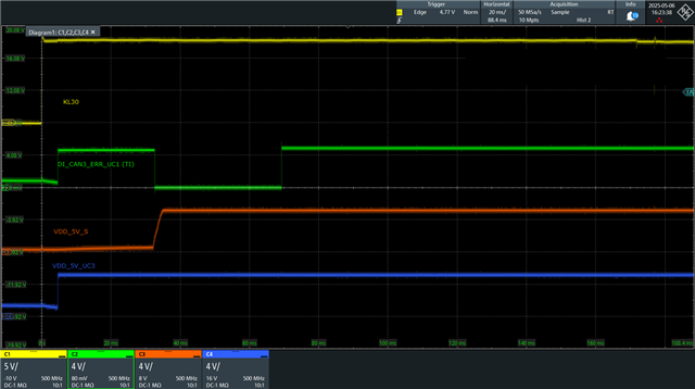
Initial condition: KL30 power on, Start CANoe configuration 

Expected behavior: ERR_N flag is cleared.

Observed behavior: ERR_N is cleared set to High from LOW in TCAN1043, but stuck to 'LOW' with second supplier CAN transceiver.

the measurement is attached. (*VDD_5V_S is source for VIO, VDD_5V_UC3 is source for VSUP and VCC). ERR_N low tigger seems to be PWRon flag.

Q1. In TCAN1043, the supply source for ERR pin is not VIO, but VSUP or VCC? What is the reason why ERR is pulled high  when VDD_5V_UC3 is supplied.

Q2. For clearing ERR_N, in other IC, It was solved with entering into Listen-only mode and wait time before entering into Normal mode. Which means there needs delay time between STB: High and EN: High. But, in case of TCAN1043, ERR_N was clear although mode transition occured directly from Sleep/Standby to Normal mode. Can you give the feedback about it? 
  • Hi Sungmin,

    Q1. It is VIO. Please help see 7.3.2.3 of the data sheet. However, note that similar to table 7-1, PWRON's flag is set when VSUP domain triggers the event implying nFAULT = L event comes from VSUP domain and not VIO I.e., once  VSUP passes UVsup, the low on the nFAULT pin indicates the power on event and transitioning to normal mode further transitions nFAULT from the low, to be released high to VIO's level. It just so happens that this example includes VIO and VSUP supplied at the same voltage level so not as apparent.

    Q2. Per the table, PWRON flags on VSUP powering-up and indicates the event on nFAULT, which clears after the device transitions to normal mode I.e., PWRON causes nFAULT = L during the initial sequence and cleared after the transition to normal. Further note that this is due to digital IOs such as nFAULT driven by VIO but the wake detection (event from initial power up) are driven by VSUP. Other suppliers may implement different sequencing requiring bus idle / listen-only stabilization before releasing the fault output while TI allows for a direct mode transition to clear the flag, thanks.

    Best Regards,

    Michael.