This thread has been locked.

If you have a related question, please click the "Ask a related question" button in the top right corner. The newly created question will be automatically linked to this question.

LMH0397: Additional Jitter Related to the CDR when Transmitting DVB-ASI Signal

Part Number: LMH0397

Hello E2E Experts,

  We're using LMH0397 to output DVB-ASI signal.On our board,there're 8 ASI channels and each one using one LMH0397.In the test of output eye diagram, we found that the jitter performance of some of these channels is poor,with jitter values reaching 400~500ps,while the normal channels are approximately 200ps.The screenshot is as follows.

Good channel:

good.jpg

Bad channel:

bad.jpg

    As we've tried all possible debugging steps per AE's suggestiongs without improvement,finally we tried to bypass the CDR module inside the LMH0397.Unexpectedly, the test result of jitter is less than 100ps, better than those with CDR enabled.

jitter with CDR bypassed:
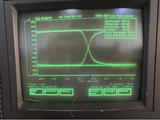
bypass.jpg

 I haven't found much descriptions about transmitting DVB-ASI signal in the LMH0397's datasheet Could you please answer the following questions?

(1)Is it a normal situation that the LMH0397 has additional jitter when transmitting DVB-ASI signals with CDR enabled?

(2)If yes,why do some of them have nearly 500ps of jitter while most of others only have 200ps?

(3)If not,are there any settings in the LMH0397's registers can improve the jitter performance?

  • Hi, 

    (1)Is it a normal situation that the LMH0397 has additional jitter when transmitting DVB-ASI signals with CDR enabled?

    Such case has not been reported so far. 

    There is no known register setting to improve jitter performance. But, it could be that the CDR is not locking to the correct rate. Have you checked the CDR lock status by reading reg 0x02[5:3] in CDR page?

    Best,
    J

  • Hi J,

    We have checked the register value per AE's suggestion,the value of reg 0x02[5:3] is 100'b,the locked data rate is 270Mbps.

  • Hi, 

    Thank you for checking the register. 
    According to the datasheet, CDR lock mode should give 0.1UI jitter whereas CDR bypass will give 0.2UI. What you are observing here is exactly opposite is definitely not an expected behavior. 

    Does this jitter behavior shown on the good channels also?

    If you haven't tried this, have you tried bypassing cable EQ and just enabling the CDR? I am unsure what the trace length here is, but the over-equalization of the signal on the RX side could cause CDR circuitry to give out signal with more jitter. 

    Best,
    J

  • Hi J,

    Thank you for your reply.

    We also test the good channel with CDR bypassed,and the jitter is also reduced to several tens of picoseconds.So I think all the channels have similar behavior.

    For your second suggestion,I only found a register setting to bypass the cable EQ in the programming guide.But in our current cable driver mode,I think it may not be effective,is it right?The trace length of all 8 channels on our board is from 4 to 5 inches,are there any other registers that we can try to adjust?

    Kind Regards,

  • Hi, 

    I see. Has the previous AE looked at the schematic? If not, would you mind sharing the schematic? Feel free to message me the schematic as this is a public forum. I've sent you a friend request so you can message me. 

    You are correct that bypassing cable EQ will not be effective for CD mode. I thought you were in EQ mode. In this case, the PCB EQ may have been over-equalized and has to be configured correctly. You can use register 3h to select different CTLE value in this case. Please refer to section 3.8.2 of the programming guide for specific programming details. 

    Please let me know. 

    Best,
    J

  • Hi J,

    This is our company's account,so i prefer to post the schematics here.One of the 8 channels' schematic as follows,IN0± and OUT0± are connected to FPGA by AC coupled.All 8 channel have same schematic and PCB layout.Our AE has checked the schematics before,and no issues were found.

    My colleague responsible for software is on a business trip now,we will try that IN0 CTLE Setting when he returns and show you the results.

    Kind Regards,

  • Hi, 

    I noticed that your jitter measurement for CDR locked signal is 10 Hz while the jitter measurement for CDR bypassed signal is 1kHz. For this device, CDR loop bandwidth at HD is about 1.5MHz and parts of the timing jitter passes through. As such, our reclocker will not be able to clean up low-frequency jitter. Sometimes or somehow low frequency noise is getting into the power supply network and affecting video source. It would be good to find the root cause of this low frequency jitter in the signal source that is being sourced to the device. 

    In addition, the jitter reported is 0.1 UI which is less than the specification of the datasheet's jitter which is 0.45 UI. 

    As such, I think this could be a normal behavior. 

    One way to verify this can be using the device's eye monitor feature. If we do so, we can eliminate possible measurement setup issue and see what the measured jitter is with and without the CDR. 

    Would you be able to try that?

    Please let me know. 

    Best,
    J

  • Hi J,
    Below are the results of our recent tests.
    1.We tuned the CTLE value from 0x00 to 0x95 with the CDR bypassed,and found no obvious changes.Then we try that with the CDR enabled,and the eye diagram is also nearly the same.We readed back the reg value to confirmed it was programmed correctly,so the CTLE value may not affect the jitter in our case.
    2.We swapped the 0397 of the high jitter channel with the part of another good channel,then found the jitter performance also swapped.Meanwhile,considering that in our previous tests,we only bypassed the CDR with no other changes on board.There may be no significant power noise on our board.
    3.The test instrument we used is the VM700,it is mainly used to measure SDI eye diagram,with a special option,it can show the ASI eye diagram too.I'm not quite sure what effects the 10/1K Hz filter setting has on measuring ASI signals,but in our test,I tried both of them and the eye diagrams are nearly the same.
    4.In the datasheet,it says the EOM is operational for 2.97Gbps and higher data rates.As the ASI signal is only 270M,can the EOM work?
    5.As my previous datasheet is an old version,I download the new one from TI's website and found the description of 0.45UI.But here is a new question,according to the SMPTE-259M standard,the threshold of timing jitter and alignment jitter both are 0.2UI.Isn't the 0.45UI of CD mode beyond the standard?

    Kind Regards,

  • Hi, 

    1.We tuned the CTLE value from 0x00 to 0x95 with the CDR bypassed,and found no obvious changes.Then we try that with the CDR enabled,and the eye diagram is also nearly the same.We readed back the reg value to confirmed it was programmed correctly,so the CTLE value may not affect the jitter in our case.
    2.We swapped the 0397 of the high jitter channel with the part of another good channel,then found the jitter performance also swapped.Meanwhile,considering that in our previous tests,we only bypassed the CDR with no other changes on board.There may be no significant power noise on our board.
    3.The test instrument we used is the VM700,it is mainly used to measure SDI eye diagram,with a special option,it can show the ASI eye diagram too.I'm not quite sure what effects the 10/1K Hz filter setting has on measuring ASI signals,but in our test,I tried both of them and the eye diagrams are nearly the same.

    Thank you for checking on these. It looks like this may be a particular device issue since the issue of increased jitter follows the device.

    4.In the datasheet,it says the EOM is operational for 2.97Gbps and higher data rates.As the ASI signal is only 270M,can the EOM work?


    You are right that EOM will not be adequate feature for 270Mbps signal. 

    5.As my previous datasheet is an old version,I download the new one from TI's website and found the description of 0.45UI.But here is a new question,according to the SMPTE-259M standard,the threshold of timing jitter and alignment jitter both are 0.2UI.Isn't the 0.45UI of CD mode beyond the standard?

    You are indeed correct that 0.45 UI is above SMPTE-SD standards. However, my understanding on this value is that the worst value was reported across validation of data rates from 270Mbps to 12G. In addition, this value was measured with a wideband measurement so it cannot be directly compared to SMPTE's timing jitter limits. I looked more into the validation data of this part, and the jitter reported for 270Mbps was 0.07 UI. 

    Based on internal discussion, it looks like increased jitter for this particular device can be a device issue especially when the issue follows the device, not the board. However, the jitter measured is still less than the 0.2 UI which is the SMPTE-SD standard as you pointed out. But, because this particular device is performing worst than other devices, I would consider that this device qualifies for a return. 

    For this, I suggest to submit a return request to TI as there really is no way to tune the jitter on this device. 

    Please let me know if you have more questions. 

    Best,
    J

  • Hi J,

    Thank you very much for your detailed and patient reply.

    I think that covers all my questions for now.We will submit a CPR request later to check if there are any issues inside the chip.

    Best regards,

  • Hi, Sounds good. Please keep us updated if you need any support from the applications side. The post will automatically close in 30 days so please feel free to open a new post with the link to this post for any previous information.

    Best,

    J