This thread has been locked.

If you have a related question, please click the "Ask a related question" button in the top right corner. The newly created question will be automatically linked to this question.

DP83867ERGZ-R-EVM: CRC errors

Part Number: DP83867ERGZ-R-EVM

Hi,

I would like to discuss with you about an issue found with TI DP83867 PHY embedded on our new boards. Let me explain test scenario and test HW setup:
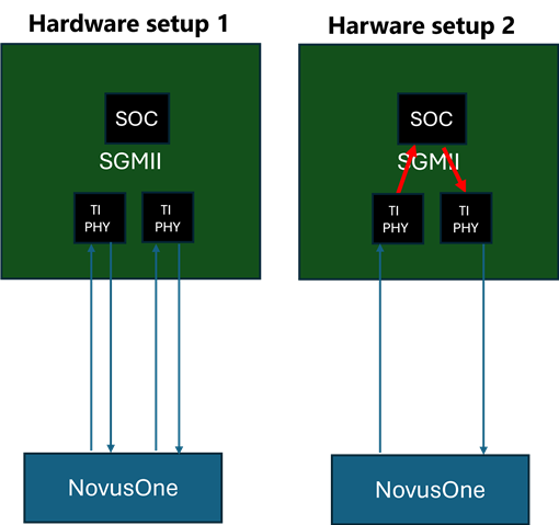
 

Hardware setup 1:

  • The DUT is connected to Keysight NovusOne equipment
  • The TI PHY DP83867 is configured in “reverse loopback mode”
  • Cable length: 2.5m


Hardware setup 2:

  • The DUT is connected to Keysight NovusOne equipment
  • The TI PHY DP83867 is configured in “normal operation mode”
  • Cable length: 2.5m


Test scenario:

  • The NovusOne equipment sends packets to the DUT with the following settings:
    • IGP: 12
    • 100% line rate used
    • Packet fixed size to 512B


àResults:

  • Runing the test scenario above on the “hardware setup 1” we observe huge amount of CRC errors at the RX side of the NovusOne equipment
  • Runing the test scenario above on the “hardware setup 2” we observe huge amount of CRC errors at the RX side of the MAC (on the DUT) connected to the PHY


Note: we have two RJ45 ports, so 2 a TI dp83867 PHY and we get the same result on both ports.


Observations:


We found in TI DP83867 troubleshooting pdf (DP83867 Troubleshooting Guide (Rev. C)) a sequence which fixes the CRC errors explained above (in both hardware setups).

Sequence mentioned page 18 in section 3.1 “Improving Link-up Margins for short Cables” fixes the issue, but we have several questions regarding it:


  • Can you explain the CRC observed ?
  • What does exactly in detail the sequence explained in section 3.1  “Improving Link-up Margins for short Cables” ?
  • Why this sequence (targeted for a cable shorter than 1m) makes our test passed whereas we use a cable of 2.5m length?
  • Are we sure that this sequence will fix CRC errors for all possible cable lengths?


Thanks in advance for your help and explanations.


Regards

Alexandre

  • Hi Alexandre, 


    • Can you explain the CRC observed ?
    • What does exactly in detail the sequence explained in section 3.1  “Improving Link-up Margins for short Cables” ?
    • Why this sequence (targeted for a cable shorter than 1m) makes our test passed whereas we use a cable of 2.5m length?
    • Are we sure that this sequence will fix CRC errors for all possible cable lengths?

    We've had customer cases in which our DSP is not converging fast enough in short cables that it caused the DSP to converge into the wrong state. In your case, it may have been the case for 2.5m cable that the DSP converges into the wrong state causing CRC errors. 

    This sequence should fix the CRC error for all cable length. 

    Best,
    J

  • Hi,

    Can you provide more details please? 

    Sorry but I have two other questions :

    - Can you confirm this "fix" covers all cable length?

    - Can you confirm this "fix" does not affect the bandwidth or latency?

    thanks

    Alexandre

  • Hi Alexandre, 

    The scripts are meant to increase the time needed for our DSP to converge. I apologize for the previous comment in which I said it makes the DSP converge faster. The script increases the internal timer so that the DSP has more time to converge as we have seen that the DSP cannot converge in time with the default timer value in the PHY in some short cables. I have edited the above comment to minimize confusion. I have not heard cases in which using this script broke link on other cable length. And the fix should not affect bandwidth or latency as this is for internal DSP convergence. 

    Best,
    J

  • Hi 

    Sorry but this sequence does not fix all my use cases. Remember, I configure the PHY in reverse loopback mode :

    - If I send packets with a size of 512B, IPG 12 and 100%line rate then Sequence mentioned page 18 in section 3.1 “Improving Link-up Margins for short Cables” fixes the CRC errors.

    - If I send packets with a random size (from 64B to 128 B), IPG 12, 100%line rate then the sequence (mentioned page 18 in section 3.1) is not enough to fix and there are still CRC errors.

    Can you please why and help us to find a solution ?

    Regards

    Alexandre

  • Hi,

    US office is closed for Thanksgiving. I will review and get back to you Monday in dallas time.

    Best,

    J

  • Hi Alexandre, 

    I apologize for the delay. 

    The scripts are meant for link-up, not for CRC errors so there still may be CRC errors. 

    Have you also tried using script in 3.2?

    Best,
    J

  • Hi,

    Let me try to explain again more in details my observations :

    Hardware setup 1:

    • The DUT is connected to Keysight NovusOne equipment
    • The TI PHY DP83867 is configured in “reverse loopback mode”
    • Cable length: 2.5m

    Test scenario:

    • The NovusOne equipment sends packets to the DUT with the following settings :
      • IGP: 12
      • 100% line rate used
      • Packet fixed size to 512B

    Firstly, I didn't add section in 3.1. It seems that something goes wrong during the link establishment for example I get this:

    --> link is up --> Run test scenario --> NO CRC (could run over the night) --> I force link down then link up --> Run test scenario --> CRC errors observed-->I force link down then link up --> Run test scenario --> CRC errors observed-->I force link down then link up --> Run test scenario --> NO CRC --> .....

    So something during the link establishment creates something bad and adding software sequence in 3.1 improves the situation (but not all use cases).

    So please help us to understand this strange behavior.

    regards

    Alex

  • Hi Alex, 

    Thank you for the clarification. 

    One thing I can see something going wrong is the Auto-MDIX resolution. You can check register 11h bits 8 and 9 to see the MDIX resolutions on pair A, B, C, and D. 

    In addition, also using the script 3.2 in the troubleshooting guide may help. 

    Best,
    J

  • Hi,

    Thanks for answer. 

    - I tried to add 3.2 sequence, but it doesn't improve the situation

    - Regarding bits 8 and 9 of PHYSTS register I observe that those bits change from a linkup to another. I get values 00 or 11, but there is no correlation with CRC errors I get or I don't get.

    regards

    alex

  • Hi Alex, 

    This can be due to master/slave configuration of the link between the DUT and the LP. 
    This is another factor that changes based on every link up. Bit 14 and 15 of register 0x000A will hold this value. Could this values be checked in the working and non-working condition?
    If this is the case, you can manually set master/slave using the bits below in register 0x0009:


    Please let me know. 

    Best,
    J

  • Hi

    I can see that sometimes these bits change but I cannot link it to my issues. For example, with values 0x3 for bit [15..14] I can get CRC errors and after link down/up with the same value, I don't get CRC errors.

    regards

    Alex

  • Hi Alex,

    I see, how often does this issue occur? Is it every other linkups, or every once in a while?

    Best,
    J

  • Hi 

    On 2 or 3 link up/down I observe the different behavior.

    regards

    alex

  • Hi Alex, 

    Is this frequency with the script in 3.1 applied? If so, what was the frequency before the 3.1 script, or vice versa?
    Also, without disconnecting the cable, is restarting the auto-negotiation fix the issue? This can be done by setting 1 to bit 9 of 0x0000 register. 

    Best,
    J

  • Hi 

    I get the same frequency with or without applying section 3.1. Section 3.1 acts on the robustness of the PHY. Without it, I observe CRC errors for packets with a fixed size of 512B, and for packets with random size. After application of section 3.1, I only see CRC errors with packet with a random size from 64B to 128B so when the PHY is more stressed. Note that in both case I don't have CRC errors if I move IPG from 12 to 13. 

    I tried to play with autoneg enable bit. Enabling this bit actually implies a link down and then a link up. So I get the same conclusion.

    regards

    Alex

  • Hi Alex, 

    Thank you for the information. Thank you also for trying the IPG. If it works without any issue when you move IPG to 13, could you try writing 0053 2053? This is supposed to change the threshold of the IPG counter in the PHY, and this is the lowest threshold the PHY supports. This is also part of the 3.1 script. Could you see if this change improves the issue?

    Best,
    J

  • Hi 

    What is the difference between 0x2053 and 0x2054  because first trials with 0x2053 instead of 0x2054 seems promising. However I need to perform more tests.

    Thanks

    Alex

  • Hi Alex, 

    Register 53 holds the the threshold value of the IPG counter in the PHY. 2053 is the lowest threshold the PHY supports. It looks like in this connection scheme that the PHY is not reading the correct IPG, or the IPG is getting lost somewhere in the connection to the PHY. 

    Best,
    J

  • Hi,

    Still no issue after changing register 0x53 from 0x2054 to 0x2053 ! As soon as I come back to 0x2054 I see CRC errors. I remember to have play with this register but looking at the datasheet, it is never specified than we can set 0x3 as value (it is either 0x5 for IPG <12 or 0x5 for IPG >=12).

    Sorry but I need more details to understand the issue and be sure that we have a fix.

    - What is the default value ? because only the line (in section 3.1) touching on the 0x53 (setting 0x2054) register improved the situation actually.

    -Why do I need to set this undocumented value ? Is it an issue with the board layout ? or another configuration of the PHY ?

    Thanks in advance

    alex  

  • Hi, 

    The default value is 0x2055. 0x5 is typically for IPG=12, and 0x4 is IPG less than 12, but it is more like IPG=11. 0x3 is known to be IPG=10, etc. 
    This value has to be set because it seems like in your connection IPG is being lost causing the IPG read at the PHY not to be 12 or 11. And this seems to be causing the CRC error. It could be issue with the board layout, or the cable could be giving a lot of loss. 

    Best,
    J


  • Hi J

    But what means "your connection IPG is being lost" ?  Because my assumption (maybe stupid) is that if the IPG is not being lost or not standard then the frame will be discarded by the MAC. Sorry but I don't see the link with the PHY.

    Regards 

    alex 

  • Hi 

    Situation seems to be better but I still have CRC errors. Frequency of up/down is lower that before (maybe 1 up/down on 10 is ko).

  • Hi Alex, 

    The IPG that the MAC can handle is as low as 8 per IEEE standard. However, our PHY was not designed to handle such low IPGs. As such, there can be a case in which the MAC does not drop the packet, but the PHY is not working well. 

    However, because it doesn't happen on every link, this may be something that is not related to the IPG, but changing the threshold helps. 

    Could you check if the XI clock frequency is 25MHz? We have seen cases in which unstable input clock can cause the PHY to give out CRC errors. 

    Best,
    J

  • Hi J

    I did more tests on my side on several boards (each boards have a different PCB layout):

    BoardA = non-optimized layout

    BoardB and C = optimized layout.

    Remember I run my test in the following condition: IPG 12 / 100% line rate.

    With Viterbi set to 0x4:  on all boards I get CRC errors:

    With Viterbi set to 0x3: Board A get CRC errors but boards B&C (with optimized layout) I don't have CRC errors.

    Now the question is:

    - Why 0x3 is not defined in your datasheet ?

    - Would it possible to add it ? or at least add it in the TI troubleshooting guideline ?

    -Is this Phy supports IPG12 at 100% line rate ?

    Thanks in advance

    Alex

  • Hi Alex, 

    - Why 0x3 is not defined in your datasheet ?

    We have known the setting, but have not yet put it in the datasheet after validation effort in the past. 


    - Would it possible to add it ? or at least add it in the TI troubleshooting guideline ?

    We will add it in both datasheet and the troubleshooting guide. 


    -Is this Phy supports IPG12 at 100% line rate ?

    Yes, the PHY supports IPG 12 at 100% line rate. 

    Best,
    J

  • Hi,

    Thanks for your answers. My latest question is: When do you think that datasheet will be updated for Viterbi ?

    thanks

    Alex

  • Hi Alex,

    The datasheet is currently expected to be revised this quarter. 

    Best,
    J