This thread has been locked.

If you have a related question, please click the "Ask a related question" button in the top right corner. The newly created question will be automatically linked to this question.

THVD4411: Consideration of RS-232/RS-485 Dual Protocol Compatible Transceivers

Part Number: THVD4411
Other Parts Discussed in Thread: THVD4421, THVD4431,

I am considering implementing a dual-protocol RS-232 / RS-485 (half-duplex) transceiver.
I am evaluating whether THVD4441, THVD4421, or THVD4431 can achieve this configuration.

The intended terminal block pin assignment is as follows:

  • RS-232 TX and RS-485 (half-duplex) “+” share the same terminal

  • RS-232 RX and RS-485 (half-duplex) “–” share the same terminal

  • RS-232 GND and RS-485 (half-duplex) GND also share the same terminal

The MCU will switch between RS-232 and RS-485 modes.
Between the MCU and the transceiver, we plan to use isolation (digital isolators and optocouplers).

Is this configuration feasible using one of the THVD44xx devices?
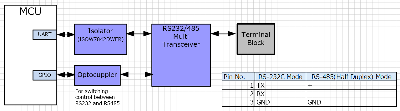
image.png

  • Hi Takanori,

    We are currently on holiday. Please help give until next week for some feedback, thanks.

    Best Regards,

    Michael.

  • With the THVD4411, the R2 pin is both the RS-232 receiver input and the RS-485 non-inverting signal. So that configuration would not be possible.

    With the THVD4421, you can connect R2 and R3 to pin 1, and R1 to pin 2. Connect the MCU's TXD signal to L3. Combine L1 and L2 with an AND gate, and connect it to the MCU's RXD signal.

    This would be easier if you would switch the two signals of one of the protocols.

  • Hi Takanori, 

    Clemens is correct. 

    -Bobby

  • Hi Clemens and Bobby,

    I am truly honored to receive your advice.

    I have personally verified the information you provided.

    I believe it can be achieved with THVD4421. Is the illustrated configuration acceptable?

    -Takanori


  • Hi Takanori,

    The RS232 set up you have causes the R3 to loop into R2. This causes the RS232 load to be 2x because if its connected to another board there will be 2x 5k resistors in parallel. The R3 RS232 output would have to work harder to drive the line. 

    It would probably still work but you will end up with more power consumption and max datarate/distance for RS232 will be affected.

    -Bobby

  • Hi Bobby,

    Previously, Clemens instructed me to connect R2 and R3 to pin 1, but that causes a loop.

    To avoid loops, we considered adding a relay-like switch to the communication line. However, if the relay is used to switch the communication line, this can already be achieved using standard RS485 transceivers and RS232 transceivers without needing the multi-transceiver THVD4421, making that approach more cost-effective.

    Is there any other good solution?

    We are also considering alternatives to the THVD4421.

    For example, using standard RS232 transceivers and RS485 transceivers, and switching the communication lines connected to the terminal block with something like a photo-MOS relay, should make this achievable. What do you think?

  • Takanori,

    Can you use THVD4411 and tie the R3 pin to the R1 pin for RS232 mode? Your RS232 map of pin 1 and pin 2 would need to swap.

    I think that would prevent the loopback and the additional RS232 loading on the transmitter that the earlier configuration had.

    -Bobby

  • Hi Bobby,

    If terminal arrangement on the terminal block can be freely determined, the THVD4411 can support both RS232 and RS485 (half-duplex mode). However, existing products pair the RS232 TX pin with the RS485 (half-duplex) + pin, requiring terminal block compatibility, so pin assignments cannot be changed.
    To swap communication lines, high-voltage multiplexers or PhotoMOS switches would likely be required, which would increase costs. Considering signal switching as a premise, using standard RS232 transceivers and RS485 transceivers might be a more cost-effective solution.

    -Takanori