This thread has been locked.

If you have a related question, please click the "Ask a related question" button in the top right corner. The newly created question will be automatically linked to this question.

AM62A7: OSPI boot mode not recognizing Micron MT35XU flash with RESET signal

Part Number: AM62A7

Hello,

I have been currently working on getting OSPI/QSPI NOR boot mode working on a AM62A-based custom board. We are using a Micron MT35XU02GCBA1G12. I have run into an issue with the SPL not being able to correctly retrieve/decode the JEDEC ID bytes during boot. Currently in SD/MMC boot mode, I am able to probe the SPI flash succesfully and report the correct JEDEC ID bytes. 

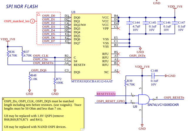
I read in the AM62Ax TRM, that because our flash device is greater than 128 Mb, we need to perform a reset using the RESET signal on the device to change the addressing mode. I have included this into my pinmux (AM62AX_IOPAD(0x0038, PIN_OUTPUT_PULLUP, 1) /* (G20) OSPI0_CSn3.OSPI0_RESET_OUT0 */) to enable the reset to occur, and it seems like we receive all 0xFF bytes from reading the JEDEC ID. If I do not include this reset within my pinmuxxing, I am able to correctly read the ID bytes but fail futher into the boot process, again. Below are snippets of the trace I have done within the SPL.

Why are we able to retrieve the correct ID bytes without toggling the signal but still fail later in the process? Why does toggling the RESET signal report 0xFF ID bytes? Should I be able to get as far as I did within the boot process with no RESET? 

With RESET signal enable:

U-Boot SPL 2025.01-gfe371093a62c-dirty (Dec 01 2025 - 17:02:44 +0000)
SYSFW ABI: 4.0 (firmware rev 0x000b '11.1.5--v11.01.05 (Fancy Rat)')
Configuring LPDDR4 for 2GB
[TRACE] am62a_init: board_init_f done
SPL initial stack usage: 13568 bytes
[TRACE] get_primary_bootmedia: __get_primary_bootmedia: bootmode = 0x1 bootmode_cfg = 0x2
[TRACE] am62a_init: spl_boot_device: devstat = 0x10b bootmedia = 0x3 bootindex = 0
[TRACE] before boot_from_devices
Trying to boot from SPI
[TRACE] In spl_load_image
[TRACE] bootdev = 3
[TRACE] spl_spi_load_image: start
[TRACE] spl_spi_load_image: sf_bus=0 sf_cs=0
[TRACE] spl_spi_load_image: calling spi_flash_probe(bus=0, cs=0, speed=1000000, mode=0)
[TRACE] bootdev->boot_device = 3
[TRACE] CQSPI_REG_CONFIG = 0x80083881
[TRACE] CONFIG_SPI_FLASH_MT35XU is enabled
[TRACE] calling spi_flash_probe
Probing SPI flash ..
[TRACE] spi_nor_read_id(): sending nor
[TRACE] cdns-ospi: opcode=0x9f, nbytes=6, buswidth=1
[TRACE] cdns-ospi: data: 18 fe ff 81 2d 06
[TRACE] mode = 0, STIG_READ = 0, STIG_WRITE = 1, READ = 2, WRITE 3
[TRACE] ret = cadence_spi_mem_exec_op = 0
[TRACE] nor->read_reg; SPINOR_OP_RDID = 9f, SPI_NOR_MAX_ID_LEN = 06, tmp = 0, nor->info->id[0] = 18
[TRACE] info->name = n25q016a
[TRACE] spi_nor_ids addr = 43c19e54 first bytes: ac fe c1
...
[TRACE] in for loop info->name
[TRACE] in info->id_len
[TRACE] NOT in memcmp; info->name = mt35xu02g, info->id[0] = 2c, id[0] = ff
...
[TRACE} spi_nor_read_id JEDEC id bytes: ff, ff, ff
[TRACE] info: 00, 00, 00
jedec_spi_nor flash@0: unrecognized JEDEC id bytes: ff, ff, ff
[TRACE] JEDEC read: 00 00 00
[TRACE] ret = spi_nor_scan = -2
spi_nor_scan(flash) failed
[TRACE] return ret = -2
SPI flash probe failed for spi_flash
[TRACE] spi_flash_probe result = 0, err = 0
[TRACE] spi_flash_probe failed: 0
SPI probe failed.
[TRACE] bus 0 cs 0 speed 1000000 mode 0
spl_load_image ret = -19
In spl_load_image #2
ret = -19, -ENODEV = -19
after boot_from_devices
SPL: failed to boot from all boot devices
### ERROR ### Please RESET the board ###

With NO RESET signal enable:

U-Boot SPL 2025.01-gfe371093a62c-dirty (Dec 01 2025 - 21:02:56 +0000)
SYSFW ABI: 4.0 (firmware rev 0x000b '11.1.5--v11.01.05 (Fancy Rat)')
Configuring LPDDR4 for 2GB
[TRACE] am62a_init: board_init_f done
SPL initial stack usage: 13568 bytes
[TRACE] get_primary_bootmedia: __get_primary_bootmedia: bootmode = 0x1 bootmode_cfg = 0x2
[TRACE] am62a_init: spl_boot_device: devstat = 0x10b bootmedia = 0x3 bootindex = 0
[TRACE] before boot_from_devices
Trying to boot from SPI
[TRACE] In spl_load_image
[TRACE] bootdev = 3
[TRACE] spl_spi_load_image: start
[TRACE] spl_spi_load_image: sf_bus=0 sf_cs=0
[TRACE] spl_spi_load_image: calling spi_flash_probe(bus=0, cs=0, speed=1000000, mode=0)
[TRACE] bootdev->boot_device = 3
[TRACE] CQSPI_REG_CONFIG = 0x80083881
[TRACE] CONFIG_SPI_FLASH_MT35XU is enabled
[TRACE] calling spi_flash_probe
Probing SPI flash ..
[TRACE] spi_nor_read_id(): sending nor
[TRACE] cdns-ospi: opcode=0x9f, nbytes=6, buswidth=1
[TRACE] cdns-ospi: data: 90 4b c2 43 08 2b
[TRACE] mode = 0, STIG_READ = 0, STIG_WRITE = 1, READ = 2, WRITE 3
[TRACE] ret = cadence_spi_mem_exec_op = 0
[TRACE] nor->read_reg; SPINOR_OP_RDID = 9f, SPI_NOR_MAX_ID_LEN = 06, tmp = 0, nor->info->id[0] = 18
[TRACE] info->name = n25q016a
[TRACE] spi_nor_ids addr = 43c19eb4 first bytes: 0c ff c1
[TRACE] in for loop info->name
[TRACE] in info->id_len
[TRACE] NOT in memcmp; info->name = n25q016a, info->id[0] = 20, id[0] = 2c
...
[TRACE] in for loop info->name
[TRACE] in info->id_len
[TRACE] NOT in memcmp; info->name = mt35xu02g, info->id[0] = 2c, id[0] = 2c
[TRACE] in memcmp; info->id = 2c, id = 2c
[TRACE] JEDEC read: 2c 5b 1c
[TRACE] Applying fixups
[TRACE] ret = spi_nor_scan = 0
[TRACE] ret = spi_flash_mtd_register(flash) = 0
[TRACE] return ret = 0
[TRACE] spi_flash_probe result = 81e003d8, err = -2116025384
[TRACE] after !flash; before spl_load_init()
[TRACE] after spl_load_init()
[TRACE] after CONFIG_IS_ENABLED(OS_BOOT)
[TRACE] before spl_load()
[TRACE] in _spl_load()
[TRACE] cdns-ospi: opcode=0x13, nbytes=64, buswidth=1
[TRACE] cdns-ospi: data: ff ff ff ff ff ff ff ff ff ff ff ff ff ff ff ff ff ff ff ff ff ff ff ff ff ff ff ff ff ff ff ff ff ff ff ff ff ff ff ff ff ff ff ff ff ff ff ff ff ff ff ff ff ff ff ff ff ff ff ff ff ff ff ff
[TRACE] mode = 2, STIG_READ = 0, STIG_WRITE = 1, READ = 2, WRITE 3
[TRACE] err = cadence_qspi_apb_read = 0
[TRACE] ret = cadence_spi_mem_exec_op = 0
[TRACE] spl_parse_board_header() ret = 0
[TRACE] spl_parse_board_header = -22
[TRACE] returning -EINVAL = -22
[TRACE] ret = spl_parse_image_header #2 = -22
[TRACE] after spl_load(); err = -22
spl_load_image ret = -22
In spl_load_image #2
ret = -19, -ENODEV = -19
after boot_from_devices
SPL: failed to boot from all boot devices
### ERROR ### Please RESET the board ###
  • Hi Jacob,

    Our expert is currently out of office. please expect a delay in response.

    Regards,

    Dilna K

  • Hi Jacob,

    Currently in SD/MMC boot mode, I am able to probe the SPI flash succesfully and report the correct JEDEC ID bytes. 

    In either of these two boot modes, upon PORz ROM does not interact with the flash.

    I read in the AM62Ax TRM, that because our flash device is greater than 128 Mb, we need to perform a reset using the RESET signal on the device to change the addressing mode. I have included this into my pinmux (AM62AX_IOPAD(0x0038, PIN_OUTPUT_PULLUP, 1) /* (G20) OSPI0_CSn3.OSPI0_RESET_OUT0 */) to enable the reset to occur, and it seems like we receive all 0xFF bytes from reading the JEDEC ID. If I do not include this reset within my pinmuxxing, I am able to correctly read the ID bytes but fail futher into the boot process, again. Below are snippets of the trace I have done within the SPL.

    Why are we able to retrieve the correct ID bytes without toggling the signal but still fail later in the process? Why does toggling the RESET signal report 0xFF ID bytes? Should I be able to get as far as I did within the boot process with no RESET? 

    Can you tell me with which boot mode did you try this?

    Also, the reset signal should be connected to the FLASH, is this connected to the flash? Also is the chosen flash, the one with reset package?

    Looking forward to your response.

    Kind Regards,

    Vaibhav

  • Hello Vaibhav,

    I tried that in OSPI boot; the logs given are also during OSPI boot. The reset signal is connected to the flash from the AM62 (Pin OSPI0_CSn3/G20) and this flash does have a dedicated RESET pin. I had also mimicked the reset toggle through a software based reset to confirm the reset pinmux did in fact perform a reset and the behavior was similar upon inspection.

    Thanks,

    Jake

  • Hello Jacob,

    Thanks for your inputs.

    I tried that in OSPI boot

    Can you share with me the boot mode pin configuration on your DUT? Give me the values of Boot Mode 0, until Boot mode 15.

    Kind Regards,

    Vaibhav

  • Vaibhav,

    Out boot mode pin configuration is 0x10B (0b0000000100001011)

    -- Jake

  • Hello Jacob,

    I verified with the flash datasheet, the flash does support the OSPI Bootmode as the command sequence matches between what ROM sends and what the flash expects.

    Now, I would like to know what all changes have you done on the DTS front?

    Please share with me a list of changes you have done, to cater to the new flash part on your board.

    Kind Regards,

    Vaibhav

  • Hi Vaibhav,

    Here is the DTS node that is included in the DTS file for the R5 SPL:

    &ospi0 {
            pinctrl-names = "default";
            pinctrl-0 = <&ospi0_pins_default>;
            bootph-all;
            status = "okay";
    
            spi_nor_flash: flash@0 {
                    compatible = "jedec,spi-nor";
                    reg = <0x0>;
                    spi-tx-bus-width = <8>;
                    spi-rx-bus-width = <8>;
                    spi-max-frequency = <25000000>;
                    cdns,tshsl-ns = <60>;
                    cdns,tsd2d-ns = <60>;
                    cdns,tchsh-ns = <60>;
                    cdns,tslch-ns = <60>;
                    cdns,read-delay = <0>;
                    bootph-all;
    
                    partitions {
                            compatible = "fixed-partitions";
                            #address-cells = <1>;
                            #size-cells = <1>;
                            bootph-all;
    
                            partition@0 {
                                    label = "ospi.tiboot3";
                                    reg = <0x0 0x80000>;
                            };
    
                            partition@80000 {
                                    label = "ospi.tispl";
                                    reg = <0x80000 0x200000>;
                            };
    
                            partition@280000 {
                                    label = "ospi.u-boot";
                                    reg = <0x280000 0x400000>;
                            };
                            
                            partition@680000 {
                                    label = "ospi.env";
                                    reg = <0x680000 0x40000>;
                            };
    
                            partition@6c0000 {
                                    label = "ospi.env.backup";
                                    reg = <0x6c0000 0x40000>;
                            };
    
                            partition@800000 {
                                    label = "ospi.rootfs";
                                    reg = <0x800000 0xf7c0000>;
                            };
    
                            partition@3fc0000 {
                                    label = "ospi.phypattern";
                                    reg = <0xffc0000 0x40000>;
                                    bootph-all;
                            };
                    };
            };
    };


    We also have the following in the *-u-boot.dtsi file for our AM62A board which is included in the DTS R5 SPL file:
    &ospi0 {
            bootph-all;
    
            spi_nor_flash: flash@0 {
                    bootph-all;
    
                    partitions {
                            bootph-all;
                    };
            };
    };


    Thanks,
    Jacob

  • Hello Jacob,

    Let me loop in another expert who can comment on the changes required to get the new flash working.

    Regards,

    Vaibhav

  • Hi Jacob, thanks for the detailed inputs so far.

    Could you please verify if the following flash is supported in sdk_dir/board-support/ti-u-boot-2025.01+git/drivers/mtd/spi/spi-nor-ids.c.

    { INFO("mt35xu02g",  0x2c5b1c, 0, 128 * 1024,  2048, USE_FSR | SPI_NOR_OCTAL_READ | SPI_NOR_4B_OPCODES) },


    If not present, please add the corresponding configuration to sdk-dir/board-support/ti-u-boot-2025.01+git/configs/am62ax_evm_a53_defconfig


    CONFIG_SPI_FLASH_MT35XU=y


    Regards,
    Harshith

  • Hello Harshith,

    Yes, the info line is in the drivers/mtd/spi/spi-nor-ids.c file and we do have CONFIG_SPI_FLASH_MT35XU enabled in our board specific defconfig.

    Thanks,
    Jacob

  • Hi Jacob,

    Thank you for clarifying.

    [TRACE] cdns-ospi: data: ff ff ff ff ff ff ff ff ff ff ff ff ff ff ff ff ff ff ff ff ff ff ff ff ff ff ff ff ff ff ff ff ff ff ff ff ff ff ff ff ff ff ff ff ff ff ff ff ff ff ff ff ff ff ff ff ff ff ff ff ff ff ff ff

    With the above clarification it looks the processor is successfully communicating with the flash but not able to read anything, could you try dumping the memory at the specified offsets for boot binaries with sf read from the working environment(SD Card) in the U-boot console.If this returns all f then the binary is missing or not flashed properly.

    Regards,
    Harshith

  • Hello Harshith,

    Below are the memory dumps at the specified offsets within the working SD card boot with no reset line enabled directly after flashing.

    => sf probe
    Probing SPI flash ..
    SF: Detected mt35xu02g with page size 256 Bytes, erase size 128 KiB, total 256 MiB
    => sf read 0x82000000 0x0 0x100
    device 0 offset 0x0, size 0x100
    [TRACE] cdns-ospi: opcode=0x7c, nbytes=256, buswidth=8
    [TRACE] cdns-ospi: data: 00 80 41 a9 63 26 00 14 f4 01 00 a8 bf 02 00 f1 04 18 00 9a 80 01 00 44 a3 00 40 f9 03 02 00 14 e4 03 00 8a 62 16 00 b9 60 86 41 a9 05 00 80 10 58 26 00 84 80 07 00 30 a0 02 40 f9 00 00 14 0b 80 02 00 51 f5 5b 40 a8 e0 03 14 0a f3 60 41 a9 fd 7b c1 b8 bf 23 01 d5 40 03 5f c6 14 0d 00 e0 d6 42 10 11 e0 03 16 82 00 92 00 52 68 4f 02 14 a0 02 00 d1 a3 03 00 0a 80 07 00 b0 20 86 41 a8 e4 03 14 aa 62 36 00 a1 05 00 80 90 40 26 00 94 a0 d9 ff b5 af 00 00 94 22 0f 00 80 00 44 01 90 80 00 16 0a 42 00 04 90 41 93 80 40 e5 30 01 14 01 02 80 52 02 00 80 d2 01 01 a0 22 00 02 80 52 b5 31 08 84 a0 02 40 e9 e1 03 06 2a 82 93 00 10 81 0f 00 84 f3 52 41 89 00 00 00 52 9f 02 00 71 f5 59 42 29 5b 7f fd 11 9a 30 01 90 20 0f 00 40 40 60 01 11 42 00 01 91 01 91 00 50 20 0d 00 f0
    [TRACE] mode = 2, STIG_READ = 0, STIG_WRITE = 1, READ = 2, WRITE 3
    [TRACE] err = cadence_qspi_apb_read = 0
    [TRACE] ret = cadence_spi_mem_exec_op = 0
    SF: 256 bytes @ 0x0 Read: OK
    => sf read 0x82000000 0x80000 0x100
    device 0 offset 0x80000, size 0x100
    [TRACE] cdns-ospi: opcode=0x7c, nbytes=256, buswidth=8
    [TRACE] cdns-ospi: data: 30 82 08 58 30 82 06 40 a0 03 02 01 02 02 14 45 fa b6 8c c5 26 c4 b5 eb 68 e2 3f 94 65 03 33 db c4 44 7c 30 0d 06 09 2a 86 48 86 f7 0d 01 01 0d 05 00 30 81 9d 31 0b 30 09 06 03 55 04 06 13 02 55 53 31 0b 30 09 06 03 55 04 08 0c 02 54 58 31 0f 30 0d 06 03 55 04 07 0c 06 44 61 6c 6c 61 73 31 27 30 25 06 03 55 04 0a 0c 1e 54 65 78 61 73 20 49 6e 73 74 72 75 6d 65 6e 74 73 20 49 6e 63 6f 72 70 6f 72 61 74 65 64 31 13 30 11 06 03 55 04 0b 0c 0a 50 72 6f 63 65 73 73 6f 72 73 31 13 30 11 06 03 55 04 03 0c 0a 54 49 20 53 75 70 70 6f 72 74 31 1d 30 1b 06 09 2a 86 48 86 f7 0d 01 09 01 16 0e 73 75 70 70 6f 72 74 40 74 69 2e 63 6f 6d 30 1e 17 0d 32 35 31 32 33 31 31 36 33 39 34 36 5a 17 0d 32 36 30 31 33 30 31 36 33 39 34 36 5a 30 81 9d 31 0b 30 09 06 03 55 04 06 13 02
    [TRACE] mode = 2, STIG_READ = 0, STIG_WRITE = 1, READ = 2, WRITE 3
    [TRACE] err = cadence_qspi_apb_read = 0
    [TRACE] ret = cadence_spi_mem_exec_op = 0
    SF: 256 bytes @ 0x80000 Read: OK
    => sf read 0x82000000 0x280000 0x100
    device 0 offset 0x280000, size 0x100
    [TRACE] cdns-ospi: opcode=0x7c, nbytes=256, buswidth=8
    [TRACE] cdns-ospi: data: d0 0d fe ed 00 18 01 13 00 00 00 38 00 17 fc c0 00 00 00 28 00 00 00 11 00 00 00 02 00 00 00 00 00 00 00 6d 00 17 fc 88 00 00 00 00 00 00 00 00 00 00 00 00 00 00 00 00 00 00 00 01 00 00 00 00 00 00 00 03 00 00 00 04 00 00 00 63 69 55 51 d6 00 00 00 03 00 00 00 04 00 00 00 54 00 00 00 01 00 00 00 03 00 00 00 22 00 00 00 48 43 6f 6e 66 69 67 75 72 61 74 69 6f 6e 20 74 6f 20 6c 6f 61 64 20 41 54 46 20 61 6e 64 20 53 50 4c 00 00 00 00 00 00 01 69 6d 61 67 65 73 00 00 00 00 00 01 61 74 66 00 00 00 00 03 00 00 00 04 00 00 00 42 80 00 00 00 00 00 00 03 00 00 00 04 00 00 00 3d 80 00 00 00 00 00 00 03 00 00 00 15 00 00 00 3a 61 72 6d 2d 74 72 75 73 74 65 64 2d 66 69 72 6d 77 61 72 65 00 00 00 00 00 00 00 03 00 00 00 05 00 00 00 2e 6e 6f 6e 65 00 00 00 00 00 00 00 03
    [TRACE] mode = 2, STIG_READ = 0, STIG_WRITE = 1, READ = 2, WRITE 3
    [TRACE] err = cadence_qspi_apb_read = 0
    [TRACE] ret = cadence_spi_mem_exec_op = 0
    SF: 256 bytes @ 0x280000 Read: OK


    It looks like it is getting flashed since the reads return not all ff? We flash the boot binaries using the following script commands:

    cd /run/media/boot-mmcblk1p1
    
    flash_erase /dev/mtd0 0 0
    flash_erase /dev/mtd1 0 0
    flash_erase /dev/mtd2 0 0
    
    cp -v tiboot3.bin /dev/mtd0 && \
    cp -v tispl.bin /dev/mtd1 && \
    cp -v u-boot.img /dev/mtd2
    
    sync


    Let me know if there is any other information I can provide with this issue.

    Thank you

  • Hi Jacob,

    The logs confirm the flash is programmed correctly with valid data at the expected offsets (0x0, 0x80000, and 0x280000).

    However, the OSPI boot is failing due to a state mismatch between the BootROM and the SPL:

    • Addressing Mismatch: Since the device is larger than 128Mb, the BootROM shifts the flash into 4-byte addressing mode. When the SPL takes over and re-initializes, it defaults to the power-on standard of 3-byte addressing, causing the two to lose synchronization.

    • Protocol Mismatch: I can see in the working logs(sf read 0x82000000 0x80000 0x100) that the bus is operating at buswidth=8 (Octal mode). In the failing logs, the SPL is attempting to communicate using buswidth=1. If the BootROM left the flash in Octal mode, it will simply ignore these 1-bit commands.

    Regards,
    Harshith

  • Thanks Harshith, stepping in for Jacob for a second.  that does sound like the problem we are seeing.

    Does TI support OSPI booting with larger than 128Mb devices?  Do you have a way to work around these issues? From what you outlined, it sounds like this would be an issue for any OSPI boot. So shouldn't u-boot SPL already expect that the BootROM would put the flash into 4-byte mode.  Are we missing a setting?

  • Since the device is larger than 128Mb, the BootROM shifts the flash into 4-byte addressing mode

    According to the TRM spruj16b Section 5.4.1 OSPI\xSPI\QSPI\SPI Boot, the BootROM only supports 3-byte address mode.  Which is correct?

  • Since this thread has gotten pretty long, I'd like to summarize what I think the current state is.

    There are several scenario described previously:

    * SD card boot with SPL OSPI0_RESET_OUT0 not muxed

    RESETSTATz resets the flash

    The Boot ROM isn't touching the OSPI at all.

    U-boot is able to probe and read from the flash okay.  

    * OPSI0 boot (0b0000000100001011) with SPL OSPI0_RESET_OUT0 not muxed

    RESETSTATz resets the flash

    Boot ROM detects flash and loads SPL.

    SPL detects flash via JEDEC however then tries to read in 1-bit mode and gets all FFs

    > Presumably the Boot ROM put us in octal mode, and so 1-bit reads are incorrect?  However if thats true why did the JEDEC reads work?

    * OPSI0 boot (0b0000000100001011) with SPL OSPI0_RESET_OUT0 muxed

    RESETSTATz resets the flash

    Boot ROM detects flash and loads SPL.

    SPL fails to detect flash, JEDEC returns FFs.  No flash read is attempted since detection failed.

    > Presumably the OSPI controller is able to reset the flash using OSPI0_RESET_OUT0. However its unclear why the SPL would then fail the JEDEC read...

  • Hi Jonathan,
    Thanks for your summary.
    As a quick check point, have we tried configuring BOOTMODE[15:0]=0273 for booting on your board?
    Best,
    -Hong

  • As a quick check point, have we tried configuring BOOTMODE[15:0]=0273 for booting on your board?

    No I was not aware that xSPI boot was for OSPI flash.  I will try it out and report back

  • Hi Jonathan,
    Yes, let's keep us posted with BOOTMODE[15:0]=0273 testing on your board.
    Best,
    -Hong

  • I got OSPI boot working.

    I think we were missing some defconfig settings.  I ended up syncing SPI related settings from the AM62x defconfig's and retesting and the board booted into u-boot without issue. This is without the RESET signal muxed and just letting the system reset handle it.

    We had some of these already but I think the biggest was the U_BOOT_OFFS wasn't set previously and u-boots default is 0x0, so it would have been reading from the wrong sector.

    diff --git a/configs/mitysom_am62ax_devkit_a53_defconfig b/configs/mitysom_am62ax_devkit_a53_defconfig
    index a3f458b6f83b..97a3c83621b3 100644
    --- a/configs/mitysom_am62ax_devkit_a53_defconfig
    +++ b/configs/mitysom_am62ax_devkit_a53_defconfig
    @@ -26,6 +26,7 @@ CONFIG_SPL_BSS_MAX_SIZE=0x80000
     CONFIG_SPL_STACK_R=y
     CONFIG_SPL_FS_FAT=y
     CONFIG_SPL_LIBDISK_SUPPORT=y
    +CONFIG_SPL_SPI_FLASH_SUPPORT=y
     CONFIG_SPL_SPI=y
     # CONFIG_SYS_MALLOC_CLEAR_ON_INIT is not set
     CONFIG_SPL_LOAD_FIT=y
    @@ -45,12 +46,12 @@ CONFIG_SPL_ENV_SUPPORT=y
     CONFIG_SPL_FS_LOAD_PAYLOAD_NAME="u-boot.img"
     CONFIG_SPL_I2C=y
     CONFIG_SPL_DM_MAILBOX=y
    -CONFIG_SPL_MTD=y
    -CONFIG_SPL_MTD_LOAD=y
    -CONFIG_SYS_MTD_U_BOOT_OFFS=0x280000
    -CONFIG_SPL_NAND_SPI_SUPPORT=y
     CONFIG_SPL_DM_SPI_FLASH=y
     CONFIG_SPL_POWER_DOMAIN=y
    +# CONFIG_SPL_SPI_FLASH_TINY is not set
    +CONFIG_SPL_SPI_FLASH_SFDP_SUPPORT=y
    +CONFIG_SPL_SPI_LOAD=y
    +CONFIG_SYS_SPI_U_BOOT_OFFS=0x280000
     CONFIG_SPL_THERMAL=y
     CONFIG_SPL_YMODEM_SUPPORT=y
     CONFIG_CMD_MEMTEST=y
    @@ -82,7 +83,6 @@ CONFIG_CLK=y
     CONFIG_SPL_CLK=y
     CONFIG_CLK_TI_SCI=y
     CONFIG_DFU_MMC=y
    -CONFIG_DFU_MTD=y
     CONFIG_DFU_RAM=y
     CONFIG_DFU_SF=y
     CONFIG_SYS_DFU_DATA_BUF_SIZE=0x40000
    @@ -106,9 +106,6 @@ CONFIG_SPL_I2C_EEPROM=y
     CONFIG_SUPPORT_EMMC_BOOT=y
     CONFIG_MMC_IO_VOLTAGE=y
     CONFIG_SPL_MMC_IO_VOLTAGE=y
    -# Disabling UHS support since SDcard voltage is not controllable
    -CONFIG_MMC_UHS_SUPPORT=n
    -CONFIG_SPL_MMC_UHS_SUPPORT=n
     CONFIG_MMC_HS200_SUPPORT=y
     CONFIG_SPL_MMC_HS200_SUPPORT=y
     CONFIG_MMC_SDHCI=y
    @@ -116,9 +113,14 @@ CONFIG_MMC_SDHCI_ADMA=y
     CONFIG_SPL_MMC_SDHCI_ADMA=y
     CONFIG_MMC_SDHCI_AM654=y
     CONFIG_MTD=y
    -CONFIG_DM_MTD=y
    -CONFIG_MTD_SPI_NAND=y
     CONFIG_DM_SPI_FLASH=y
    +CONFIG_SPI_FLASH_SFDP_SUPPORT=y
    +CONFIG_SPI_FLASH_SOFT_RESET=y
    +CONFIG_SPI_FLASH_SOFT_RESET_ON_BOOT=y
    +CONFIG_SPI_FLASH_SPANSION=y
    +CONFIG_SPI_FLASH_S28HX_T=y
    +CONFIG_SPI_FLASH_STMICRO=y
    +CONFIG_SPI_FLASH_MT35XU=y
     CONFIG_PHY_TI_DP83867=y
     CONFIG_PHY_FIXED=y
     CONFIG_TI_AM65_CPSW_NUSS=y
    diff --git a/configs/mitysom_am62ax_devkit_r5_defconfig b/configs/mitysom_am62ax_devkit_r5_defconfig
    index 298e121af696..a6c8afd26e49 100644
    --- a/configs/mitysom_am62ax_devkit_r5_defconfig
    +++ b/configs/mitysom_am62ax_devkit_r5_defconfig
    @@ -9,6 +9,8 @@ CONFIG_K3_IODDR=y
     CONFIG_TARGET_MITYSOM_AM62AX_R5_DEVKIT=y
     CONFIG_HAS_CUSTOM_SYS_INIT_SP_ADDR=y
     CONFIG_CUSTOM_SYS_INIT_SP_ADDR=0x43c3a7f0
    +CONFIG_SF_DEFAULT_SPEED=25000000
    +CONFIG_SF_DEFAULT_MODE=0
     CONFIG_ENV_OFFSET=0x3E1000
     CONFIG_SPL_DM_SPI=y
     CONFIG_DEFAULT_DEVICE_TREE="k3-am62a7-r5-mitysom-devkit"
    @@ -27,6 +29,7 @@ CONFIG_SPL_SIZE_LIMIT=0x3A7F0
     CONFIG_SPL_SIZE_LIMIT_PROVIDE_STACK=0x3500
     CONFIG_SPL_FS_FAT=y
     CONFIG_SPL_LIBDISK_SUPPORT=y
    +CONFIG_SPL_SPI_FLASH_SUPPORT=y
     CONFIG_SPL_SPI=y
     CONFIG_SPL_LOAD_FIT=y
     CONFIG_SPL_LOAD_FIT_ADDRESS=0x80080000
    @@ -47,13 +50,15 @@ CONFIG_SYS_MMCSD_RAW_MODE_U_BOOT_SECTOR=0x400
     CONFIG_SPL_DMA=y
     CONFIG_SPL_I2C=y
     CONFIG_SPL_DM_MAILBOX=y
    -CONFIG_SPL_MTD=y
    -CONFIG_SPL_MTD_LOAD=y
     CONFIG_SPL_DM_SPI_FLASH=y
     CONFIG_SPL_DM_RESET=y
     CONFIG_SPL_POWER_DOMAIN=y
     CONFIG_SPL_RAM_DEVICE=y
     CONFIG_SPL_REMOTEPROC=y
    +# CONFIG_SPL_SPI_FLASH_TINY is not set
    +CONFIG_SPL_SPI_FLASH_SFDP_SUPPORT=y
    +CONFIG_SPL_SPI_LOAD=y
    +CONFIG_SYS_SPI_U_BOOT_OFFS=0x80000
     CONFIG_SPL_THERMAL=y
     CONFIG_SPL_YMODEM_SUPPORT=y
     CONFIG_HUSH_PARSER=y
    @@ -100,9 +105,14 @@ CONFIG_MMC_SDHCI_ADMA=y
     CONFIG_SPL_MMC_SDHCI_ADMA=y
     CONFIG_MMC_SDHCI_AM654=y
     CONFIG_MTD=y
    -CONFIG_DM_MTD=y
    -CONFIG_MTD_SPI_NAND=y
     CONFIG_DM_SPI_FLASH=y
    +CONFIG_SPI_FLASH_SFDP_SUPPORT=y
    +CONFIG_SPI_FLASH_SOFT_RESET=y
    +CONFIG_SPI_FLASH_SOFT_RESET_ON_BOOT=y
    +CONFIG_SPI_FLASH_SPANSION=y
    +CONFIG_SPI_FLASH_S28HX_T=y
    +CONFIG_SPI_FLASH_STMICRO=y
    +CONFIG_SPI_FLASH_MT35XU=y
     CONFIG_PINCTRL=y
     # CONFIG_PINCTRL_GENERIC is not set
     CONFIG_SPL_PINCTRL=y

    I also noticed that the kernel was reverse ordering the mtd partitions... I've never seen that before, rather annoying

    [13:14:33.967] root@mitysom-am62ax:~# uname -a
    [13:14:35.274] Linux mitysom-am62ax 6.12.43-g-g26975df2e66f #1 SMP PREEMPT Tue Dec 30 20:22:52 UTC 2025 aarch64 GNU/Linux
    
    root@mitysom-am62ax:~# cat /proc/mtd 
    [13:13:24.231] dev:    size   erasesize  name
    [13:13:24.231] mtd0: 00040000 00020000 "ospi.phypattern"
    [13:13:24.231] mtd1: 0f7c0000 00020000 "ospi.rootfs"
    [13:13:24.232] mtd2: 00040000 00020000 "ospi.env.backup"
    [13:13:24.232] mtd3: 00040000 00020000 "ospi.env"
    [13:13:24.232] mtd4: 00400000 00020000 "ospi.u-boot"
    [13:13:24.232] mtd5: 00200000 00020000 "ospi.tispl"
    [13:13:24.235] mtd6: 00080000 00020000 "ospi.tiboot3"
    
    root@mitysom-am62ax:~# cd /run/media/boot-mmcblk1p1
    root@mitysom-am62ax:~# flash_erase /dev/mtd6 0 0
    root@mitysom-am62ax:~# flash_erase /dev/mtd5 0 0
    root@mitysom-am62ax:~# flash_erase /dev/mtd4 0 0
    root@mitysom-am62ax:~# cp tiboot3.bin /dev/mtd6
    root@mitysom-am62ax:~# cp tispl.bin /dev/mtd5
    root@mitysom-am62ax:~# cp u-boot.img /dev/mtd4

    Yes, let's keep us posted with BOOTMODE[15:0]=0273 testing on your board.

    Both XSPI and OSPI bootmodes are working.  I timed them and they both took about 2.874s to reach the "press any key" prompt.

    Would you'd recommend we pick one over the other?

  • Hi Jonathan,
    It is good to know you worked out booting from OSPI-NOR on your board.
    For some OSPI-NOR flash, the default boot mode is "x1 Default Boot", either xSPI or SPI boot mode need to configured via BOOTMODE[15:0] in order to boot tiboot3.bin by ROM from OSPI-NOR.
    Best,
    -Hong

  • I also managed to fix our AM62x OSPI boot by Hi-Z pinmuxing the OSPI reset pin.  I'm not sure why but the OSPI0_RESET_OUT1 does not seem to work. 

    diff --git a/arch/arm64/boot/dts/ti/k3-am62x-mitysom-som.dtsi b/arch/arm64/boot/dts/ti/k3-am62x-mitysom-som.dtsi
    index c562eed2d0cd..73077bc3b8b4 100644
    --- a/arch/arm64/boot/dts/ti/k3-am62x-mitysom-som.dtsi
    +++ b/arch/arm64/boot/dts/ti/k3-am62x-mitysom-som.dtsi
    @@ -260,7 +260,7 @@ AM62X_IOPAD(0x024, PIN_INPUT, 0) /* (H25) OSPI0_D6 */
                            AM62X_IOPAD(0x028, PIN_INPUT, 0) /* (J22) OSPI0_D7 */
                            AM62X_IOPAD(0x008, PIN_INPUT, 0) /* (J24) OSPI0_DQS */
                            AM62X_IOPAD(0x0034, PIN_INPUT_PULLUP, 7) /* (H21) OSPI0_CSn2.GPIO0_13 SOM:OSPI_INTn_0 NC(R42) external pullup */
    -                       AM62X_IOPAD(0x0038, PIN_OUTPUT, 1) /* (E24) OSPI0_CSn3.OSPI0_RESET_OUT0 SOM:OSPI_RESET_GPIO external pullup */
    +                       AM62X_IOPAD(0x0038, PIN_OUTPUT, 7) /* (E24) OSPI0_CSn3.GPIO0_14 SOM:OSPI_RESET_GPIO external pullup */
                    >;
            };

  • Hi Jonathan,
    It is good to know that OSPI-NOR boot works via using RESETSTATz on your board.
    Best,
    -Hong