TMDS171: TMDS171 resister setting

Part Number: TMDS171


Hi All,


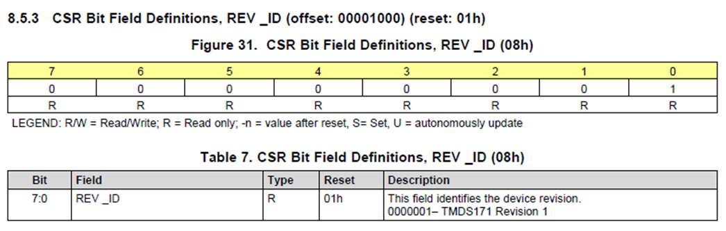
Please kindly tell me "Table 7. CSR Bit Field Definitions, REV _ID (08h)" in "8.5.3 CSR Bit Field Definitions, REV _ID (offset: 00001000) (reset: 01h)" contents.
I think that this 08h register should normally read 01h in Revision, but it reads 00h instead.
I'm sorry but, would you kindly tell me why 00h is being read out instead of 01h?

image.png

Best Regards,
Hayashi

  • Hayashi-san

    Register 0x08 provides the revision ID of the TMDS171 DIE. If they read the register 0x00 to 0x07, are they able to read correctly the DEVICE_ID? 

    Thanks

    David

  • Hi David-san,

    Thank you for your answer.
    The DEVICE_ID registers are not read sequentially starting from offset 00h as specified.
    I think the DEVICE_ID register is read in order starting from offset 00h, rather than by specifying an address.
    Is the offset readout setting not set correctly?
    If there is a basic setup method, please kindly tell me know.
    Is there any information I need to give you for you to analyze?

    Best Regards,
    Hayashi

  • Hayashi-san

    If they read the DEVICE_ID register one by one, are they able to read the correct DEVICE_ID?

    Both DEVICE_ID and REV_ID are read only registers, I am trying to differentiate the issue between the I2C setup or device. If DEVICE_ID is able to read correctly, then the I2C setup is ok and they may have an older TMDS171 unit.

    Thanks

    David

  • Hi David-san,

    We cannot read the correct value from the DEVICE_ID register one by one.
    We are understanding that DEVICE_ID and REV_ID are read-only registers.
    However, we may not have set the DEVICE_ID register read correctly.
    I'm sorry but, would you kindly tell me the correct way to read setting the DEVICE_ID register?

    Best Regards,
    Hayashi

  • Hayashi-san

    DEVICE_ID and REV_ID are read-only registers, you can not set them. 

    To read these registers,

    • Pull I2C_EN to VCC of 3.3V with a 65k resistor
    • TMDS171 I2C Device Address are set by the A0 and A1 pins as shown below. 
    • Please note for 7-bit addressing, you need to add a '0' in front of Bit 7.
    • So for I2C Device Address
    A1/A0 Address
    00 0x5E
    01 0x5D
    10 0x5C
    11 0x5B
    • Once the correct I2C Device Address, you can then access a specific register. In this case, we want to read register 0x00 to 0x08.

    Thanks

    David

  • Hi David-san,

    Thank yo for your answer.
    I checked the circuit and found that I2C_EN was pulled up with 0 ohms resistor.
    I used 68k ohms resistor instead of 65k ohms resistor and connected I2C_EN to Vcc (3.3V).
    The reason I used a 68k ohms resistor is because a 65k ohms resistor is not commonly available.
    However, the situation remains unchanged, and the A0 and A1 pins remain L(Low).
    I will send you the waveform I measured with an oscilloscope.
    Does the resistor used for pull-up have to be 65k ohms resistor?

    /cfs-file/__key/communityserver-discussions-components-files/138/I2C_5F00_EN-Waveform-Data.xlsx

    Best Regards,
    Hayashi

  • Hi Hayashi-san, 

    Does your i2c controller take 7 bit or 8 bit I2C address? Based on the waveform, it looks like some readings are happening, but DEVICE_ID and REV_ID are being misread. Could you confirm that by setting other R/W registers with a dummy value and see if that value holds?

    For I2C_EN pin, as long as it is over 2.6V (VIH), that should be read as high. 


    Best,
    J

  • Hi J-san,

    Thank you for your answer.
    We use 7-bit I2C addresses for our I2C controller.
    We send BCh when writing and BDh when reading, so we think it's normal.

    About writing for registers
    We wrote 08h to offset 09h at startup, and then write 02h to offset 09h a few seconds later.
    Then we do the Read.

    Regarding read data after writing
    After writing the above, 00h is read out from Offset 09h, which means that the correct data was not read.

    I'm sorry many questions!

    Best Regards,
    Hayashi

  • Hi Hayashi-san, 

    Have you checked SCL and SDA connection to the chip? Is SCL and SDA nets connected to SCL and SDA pins?
    Also, does SCL and SDA have pullup of 2k to VCC? Also, does the 12c controller support the same VCC level as TMDS171?

    Best,
    J

  • Hi J-san,

    As far as I can tell from checking the netlist on the board, there are no problems with the connection between I2C and TMDS171.
    I2C_SCL is connected to TMDS171 (terminal 15), and I2C_SDA is connected to TMDS171 (terminal 16).
    SCL and SDA are each pulled up to VCC with 2kΩ (there are no other connections).
    The I2C controller also has the same VCC level (3.3V) as the TMDS171.
    The pull-up resistors are connected to VCC_1 and VCC_2 of the TMDS171.

    Best Regards,
    Hayashi

  • Hayashi-san

    • Please note for 7-bit addressing, you need to add a '0' in front of Bit 7.
    • So for I2C Device Address
    A1/A0 Address
    00 0x5E
    01 0x5D
    10 0x5C
    11 0x5B

    If you use the I2C address as shown above, are you able to read/write the register correctly?

    Thanks

    David