This thread has been locked.

If you have a related question, please click the "Ask a related question" button in the top right corner. The newly created question will be automatically linked to this question.

THVD1450: RS485 communication fails when multiple slaves

Part Number: THVD1450
Other Parts Discussed in Thread: THVD1400

Hi team,

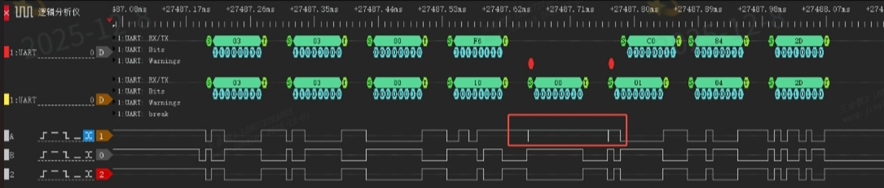
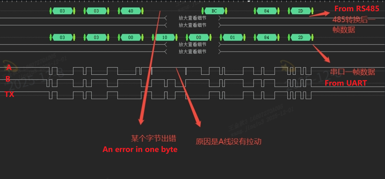
The communication works normally when the THVD1450 is used between the MCU and a single slave device. However, intermittent timeout issues occur after adding a second slave. Through waveform capture, we confirmed that the serial data sent by the MCU is correct, but errors arise after the data passes through the THVD1450.
image.png

image.png

image.png

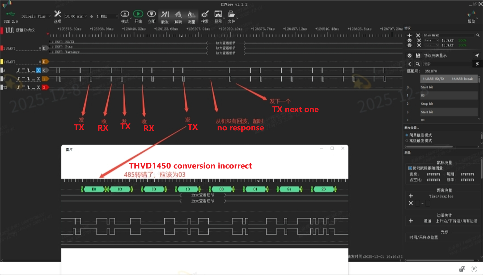
Key configuration details are as follows:
 
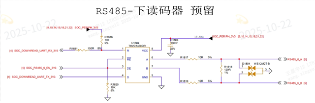
- Termination resistor: 120 ohms
- Baud rate: Initially 115200, later lowered to 19200 (no improvement observed)
 
Could you please help analyze the various potential causes of this issue? i would also appreciate guidance on the direction for debugging.

Regards,

Eileen

  • Eileen,

    Do you have a schematic of the system? (Of each RS485 transceiver)

    Do you also have a block diagram of what the bus looks like? 

    -Bobby

  • Hi Bobby,

    Please check the schematic below.

    Draft block diagram of RS485 bus:

    BUS waveform from scope when communicate normally:

    The customer attempted to add terminal resistor, as well as a 9.1kohm pull-up resistor on A and a 9.1kohm pull-down resistor on B (refer to the RS485 EVM). But none of these measures improved. Hope you give some suggestions. Thank you.

    Regards,

    Eileen

  • I would appreciate it if you could give a debugging direction first!

  • Please check the schematic below.

    I don't see any issues with the schematic. The 10 resistors on A/B can weaken the drive strength of the device (limiting the max distance and datarate) but I don't immediately think this is the issue.

    Draft block diagram of RS485 bus:

    Do we have the schematic of the RS485 device on the Radar module?

    BUS waveform from scope when communicate normally:

    Can you get a scopeshot using the math function of A-B of both the passing and failing waveform? 

    Is it possible to check if the other modules are driving at the same time our device is? That would be one of the first things I would assume would cause data errors. 

    Can you also tell me how long the cable is? 

    -Bobby

  • Hi Bobby,

    The customer also doesn't have the schematic of Radar module, but the RS485 device in it is WS3080EESA.

    A-B of passing waveform:

    The waveform shown in the main body of my post is the abnormal signal acquired via the logic analyzer. Owing to the technical limitations of the customer’s equipment, capturing this specific abnormal waveform with an oscilloscope remains challenging for their team.

    There is no other module driving at the same time.  And the second slave device was only connected and powered on, and it didn't communicate with the host at all.

    The length of the host cable is about 1m, and the slave cable is about 1.45m, with a total length of roughly 2.45m.

    Regards,

    Eileen

  • Hi Eileen,

    I don't think the issue is reflections if the distance is so short. Especially if your baudrate is so slow.

    I need to see the A-B signals of the failing waveform to understand if the issue is analog related (to our device).

    Is it impossible for us to look at the A-B scopeshots on either the main customer board or the Radar modules?

    Do we know what RS485 transceiver is on the Radar modules?

    There is no other module driving at the same time.  And the second slave device was only connected and powered on, and it didn't communicate with the host at all.

    Is there anyway we can verify if there is something wrong with the other module from a PCB standpoint?

    Can you also try adding a pull up resistor on A (700 ohms) and a pull down resistor on B (700 ohms) and verify if the issue continues?

    -Bobby

  • Hi Bobby,

    I need to see the A-B signals of the failing waveform to understand if the issue is analog related (to our device).

    Is it impossible for us to look at the A-B scopeshots on either the main customer board or the Radar modules?

    The customer reported that they couldn’t capture the abnormal waveform with an oscilloscope—extending the time base would lead to distortion, and the constantly toggling communication signal cannot be triggered. Or could you share an effective oscilloscope capture method?

    Do we know what RS485 transceiver is on the Radar modules?

    The RS485 transceiver on radar module in it is WS3080EESA.

    Is there anyway we can verify if there is something wrong with the other module from a PCB standpoint?

    Three identical slave modules were tested, and abnormalities showed up in all pairwise exchanges, making it impossible to pinpoint a faulty module.

    Can you also try adding a pull up resistor on A (700 ohms) and a pull down resistor on B (700 ohms) and verify if the issue continues?

    Pull-up resistor on A and pull-down on B tests: 680Ω caused continuous communication errors; increasing to 1.5kΩ resulted in frame loss and a higher error rate than without resistors.

    The customer is asking: What is the basis for adding pull-up/down resistors? If it’s for adjusting waveform rise/fall times, what are the standard thresholds? If the current times meet standards, is it unnecessary to add the bias resistors?

    Could you suggest some alternative debugging approaches based on your experience? It would be helpful if you could also note the technical rationale behind each method.

    Regards,

    Eileen

  • Without scopeshots all I can do is guess.

    What is the basis for adding pull-up/down resistors?

    Adding external resistors can help if there is noise on the bus. Devices without internal fail safe biases get additional noise margin during idle periods or when the active driver is disabled. I usually recommend external resistors for this reason (atleast have them on the PCB and can populated later if needed).

    If it’s for adjusting waveform rise/fall times, what are the standard thresholds?

    It is not for rise/fall time. We don't have a standard threshold from an RS485 point of view. The rule of thumb I usually see is to have the rise/fall time be equal to or less than 1/3 of the bit period. At your data rate and with our THVD1450 and cable distance, you have more than enough margin in rise/fall times vs. bit period.

    If the current times meet standards, is it unnecessary to add the bias resistors?

    It's for noise immunity. Again, without scopeshots I assumed the issue might have been noise related. If adding them made it worse, then it isn't a noise issue. But it sounds like it may be related to the current somehow. 

    Could you suggest some alternative debugging approaches based on your experience? It would be helpful if you could also note the technical rationale behind each method.

    Again, without scopeshots I will be making random guesses. Here is a list of guesses.... (Also note, I am not able to find an English datasheet for that WS3080 device so I am using the Chinese one and making some guesses)

    1) If there are any termination resistors on the radar module, remove them. If multiple boards have 120 ohm resistors, that will cause the VoD to become smaller and make it harder to detect/see the transmitted signal. WS3080 has a ViD of -200mV for a logic low and requires a ViD of 10mV for a logic high. If there are 3x 120 ohm resistors in paralllel, this would make the resistance 40 ohms. The VoD of our driver will get smaller as the parallel resistance gets smaller. 

    2) Our device's fast rise/fall time is somehow causing the WS3080 to trigger its esd protection. Try sampling a THVD1400 and see if the issue still persists. THVD1400 has slower rise/fall times which could be helpful if this is happening.

    3) Similar reason to above but placing a cap in parallel with the 120 ohm resistor (you can just populate it on top of R1818) can slow down the edge rates and help with any kind of edge rate skew between A/B. Try 1nF. 

    4) replace the WS3080 with THVD1450 just to check and see if it's related to the transceiver or the board. 

    5) replace THVD1450 U1804 to verify if the device is damaged.

    -Bobby