This thread has been locked.

If you have a related question, please click the "Ask a related question" button in the top right corner. The newly created question will be automatically linked to this question.

DS90UB947-Q1EVM: FPD-link flickers

Part Number: DS90UB947-Q1EVM
Other Parts Discussed in Thread: DS90UB947-Q1, DS90UB948-Q1, ALP

Hello! When verifying our self-designed DS90UB947-Q1/DS90UB948-Q1 PCBA, the screen flickers continuously.

However, color display is normal. The touch panel on the LCM and the LP-8866-Q1 backlight brightness I2C control via FPD-link are functioning normally.

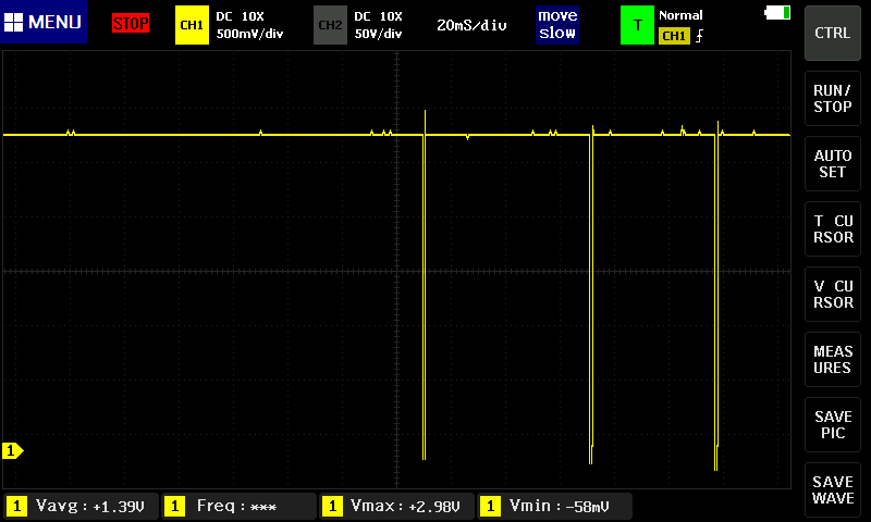
I2S is not used in this application. The LCD resolution is 1920x720, and the FPD-link cable length is 2 meters. Improving the power supply did not significantly improve the situation. The LOCK LED indicator on the DS90UB948-Q1 exhibits intermittent fluctuations.

The functionality was verified on an EVB before implementing the PCBA.

It is worth noting that the flickering problem was resolved after replacing the DS90UB947-Q1 or DS90UB948-Q1 with an EVB.

Therefore, we believe the problem lies in the FPD-link signal quality. However, our company lacks high-speed equipment for measuring FPD-link waveforms.

Even if we can measure the problem, we can't pinpoint its exact location.

Comparing the EVB signal to the temporary registers in our self-designed PCBA… we found no significant difference.

Therefore, I would like to ask which part of the temporary registers can be modified, or how to modify external components.

Attached is a video of LCM flickering and the lock signal waveform.Lock_waveform.bmp

  • Hi Kelly,

    Welcome to the E2E forum!

    I have the following questions regarding this system system

    • Is this single or dual FPD-Link?
    • What type of cable is used?
      • STP, coax
      • Connector
    • How many UB947/UB948 PCBAs have been produced? Does the flicker show up on multiple units?

    Therefore, we believe the problem lies in the FPD-link signal quality. However, our company lacks high-speed equipment for measuring FPD-link waveforms.

    There is a tool that can help check the signal margin to see if the signal quality is suspect. There is a Margin Analysis Program (MAP) included in the DS90UB948 ALP profile. 

    MAP App Note: Link

    Other items to check

    • 947 and 948 PDB pin voltage
      • If the voltage on PDB is unstable, this can cause device resets
    • Try different cable length
      • Shorter cable length will experience less attenuation
    • 947 Pattern Generation (PATGEN)
      • The 947 ALP profile has a tab to set the PATGEN resolution and timing. Using a lower video resolution is one way to check if this is a signal issue.

    Best,

    Jack

  • Hi Jack:

    1. I believe this is a single-channel FPD-Link because the 947's mode_SEL is 0x99.
    2. We used an STP package, just like the EVB-947 P1.
    3. We produced 20 sets (947 + 948). I tested two sets, and the results were the same.
    4. The PDBs for the 947 and 948 are fine because the PDB pull-up resistors are 10K ohms.
    5. We need more time to modify the shorter cables and the lower resolution LCD.
    6. I later added margin analysis code to RX MCU, but I tested two combinations: Real_TX + EVB_RX and EVB_TX + EVB_RX.
    The results seem to show some differences. How can I adjust the registers to fine-tune the signal ?

    REAL_TX -> EVB_RX SP
    EQ 0 1 2 3 4 5 6 7 8 9
    0 0.5 1 1 1 1 1 1 1 1 0.8
    1 0.6 1 1 1 1 1 1 1 1 0.7
    2 0.4 1 1 1 1 1 1 1 1 0.8
    3 0.1 1 1 1 1 1 1 1 1 0.7
    4 0.2 1 1 1 1 1 1 1 1 0.7
    5 0.5 1 1 1 1 1 1 1 1 0.8
    6 0.6 1 1 1 1 1 1 1 1 0.9
    7 0.4 1 1 1 1 1 1 1 1 0.6
    8 0.8 1 1 1 1 1 1 1 1 0.8
    9 0.4 1 1 1 1 1 1 1 1 0.7
    10 0.7 1 1 0.9 1 1 1 1 1 0.9
    11 0.8 1 1 1 1 1 1 1 1 0.5
    12 0.7 1 1 1 1 1 1 1 1 0.7
    13 0.7 1 1 1 1 1 1 1 1 1
    14 0.3 1 1 1 1 1 1 1 1 0.8

    EVB_TX -> EVB_RX SP
    EQ 0 1 2 3 4 5 6 7 8 9
    0 0.7 1 1 1 1 1 1 1 1 1
    1 0.6 1 1 1 1 1 1 1 1 1
    2 0.8 1 1 1 1 1 1 1 1 1
    3 0.5 1 1 1 1 1 1 1 1 1
    4 0.5 1 1 1 1 1 1 1 1 0.9
    5 0.5 1 1 1 1 1 1 1 1 1
    6 0.7 1 1 1 1 1 1 1 1 1
    7 0.7 1 1 1 1 1 1 1 1 0.9
    8 0.2 1 1 1 1 1 1 1 1 1
    9 0.7 1 1 1 1 1 1 1 1 0.9
    10 0.3 1 1 1 1 1 1 1 1 1
    11 0.9 1 1 1 1 1 1 1 1 0.9
    12 1 1 1 1 1 1 1 1 1 0.9
    13 1 1 1 1 1 1 1 1 1 0.9
    14 0.9 1 1 1 1 1 1 1 1 1
  • Hi Kelly,

    1. I believe this is a single-channel FPD-Link because the 947's mode_SEL is 0x99.

    Is the 0x99 from a specific register on the 947?

    2. We used an STP package, just like the EVB-947 P1.

    Are you using HSD connectors then?

    4. The PDBs for the 947 and 948 are fine because the PDB pull-up resistors are 10K ohms.

    Are you sequencing the 947 and 948 PDB pins according to the power sequencing requirements?

    6. I later added margin analysis code to RX MCU, but I tested two combinations: Real_TX + EVB_RX and EVB_TX + EVB_RX.
    The results seem to show some differences. How can I adjust the registers to fine-tune the signal ?

    Which script were you using to run the MAP program? If you use ALP, it will output a visual indication of the EQ/Strobe combinations that can maintain lock. The above results don't show much difference for the channel margin but I want to make sure the MAP was run as I expect.

    Do you have the registers for the 947 and 948 on the EVM and the PCBA? These can be compared to see if there is an obvious difference. 

    Best,

    Jack