This thread has been locked.

If you have a related question, please click the "Ask a related question" button in the top right corner. The newly created question will be automatically linked to this question.

DS280DF810: DS280DF810 issue follow up

Part Number: DS280DF810

Hi Drew and Greg,

Per talked, please help to share below register information:

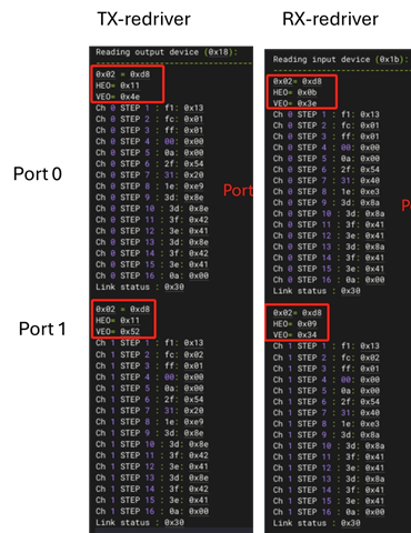
  1. The register/operation that can indicate the CDR locked status. à customer can use it to check whether the link up-down issue is a CDR locked issue.
  2. The register/operation that indicates eye opening. à customer can use it to check the eye signal quality.
  3. The register/operation that can check whether the adaptive CTLE be enabled successfully.

BRs,

Rannie

  • Hi Rannie,

    Adding your update from email

    Updating more test results today.


    To simplify the test and find the root cause, customer only connected port0 and port1 for loop back test and found the connection can link up occasionally. So, they dump the registers of 0x02 and eye opening on both situations: 1) link up (stable), 2) jump between link up and link down(unstable).


    Questions:

    1. The 0x02 are always 0xd8, which indicates the CDR locked and CLTE adaption complete (refer to table 8-3 channel register in programming guide). Why the link is still unstable?
    2. The HE0 and VE0 of TX are same whenever the link is stable or unstable. The HE0 and VE0 of RX has difference. Does that means that the TX path(CPU to redriver to SFP) is ok?
    3. Are the HE0 and VE0 measured the signal on  ①,④ or ②③? That is, the eye opening parameter is before redriver or after redriver?

    Link up:

    Link up - link down swap(unstable):

  • Hi Rannie,

    1. Link could be unstable due to high BER.  This could be a result of some sub-optimal adaptation, indicated by reduced HEO/VEO.

    2. This is a good indicator that TX path is ok.  The best way to check would be to enable PRBS31 generator on CPU.  Customer can use DS280DF810 PRBS checker to identify what part of link errors come from.

    3. The eye opening is a measurement of the signal after the CTLE and DFE RX equalization.  This is most similar to (1) and (4) in your block diagram.

    Is it possible to get register dump in stable and unstable conditions?  We can compare these to see if there is difference in CTLE or DFE values that the retimer adapted to.

    I have a few additional suggestions:

    • Since insertion loss from SFP to retimer is very low and customer is testing with optical module, customer can try forcing CTLE=0 for the optical module test case on RX channels.  See "Set CTLE Boost Value" in programming guide.
      • In addition to setting CTLE=0, customer can also try setting channel register 0x1A[3]=0 and channel register 0x13[2]=1.  This slightly reduces CTLE boost and enables the final CTLE stage to act as limiting amplifier.  This can help in some cases of over equalization.
    • Since vertical eye opening is low, customer can try adjusting the VGA to see if this improves eye opening.  See "Set Variable Gain Amplifier (VGA) and CTLE DC Gain Mode" in programming guide.

    Thanks,

    Drew

  • Hi Drew,

    Thanks for your reply.

    Update the latest test results:

    The customer has recently found that setting the device Tx and Rx to Adapt Mode 2 improve the link stability.

    They would like to confirm which of the following is the correct configuration procedure. For instance, when setting the adaptive mode for all channels, what should the exact steps be?
    1. Select channel → Select broadcast mode → Set Adapt mode
    2. Select channel → Select broadcast mode → Perform channel reset → Assert CDR reset → Set mode → Release CDR reset
    Since the three actions (channel reset, Assert CDR reset, and Release CDR reset) are all listed in the table, the customer wants to verify whether these three steps are mandatory, as the configuration seemed to take effect even without configuring them.

    BRs,

    Rannie

  • Hi Rannie,

    Thanks for the update.  Glad to hear that adapt mode 2 has improved link stability.

    Since the three actions (channel reset, Assert CDR reset, and Release CDR reset) are all listed in the table, the customer wants to verify whether these three steps are mandatory, as the configuration seemed to take effect even without configuring them.

    Channel reset is not strictly mandatory.  This is just to ensure channel registers are in a known state.  In other words, this resets any previous configuration.

    I would recommend keeping the assert CDR reset / release CDR reset.  These force re-adaptation to occur and creates a more predictable outcome.

    Thanks,

    Drew