AM26C32: AM26C32IDR waveform loss issue.

Expert 2050 points
Part Number: AM26C32


Hi Team,

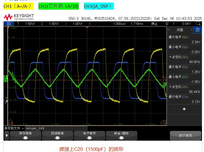
Problem point: During the retesting process, we found that the waveform amplitude at the input of chip 1A/1B with model AM26C32IDR is+1.25V - -1.35V, and there will be wave loss phenomenon later (collected by the upper computer), with a wave frequency of 500KHz.
Verification measures:
Later on, we conducted testing experiments by removing the C20 (1500pF) capacitor, increasing the amplitude to+2.87V -2.61V, and there was no wave drop phenomenon afterwards.
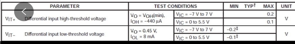
Adding the C20 capacitor reduces the amplitude to+1.25V - -1.35V, and wave loss will occur later. However, the minimum voltage input to the chip pin is 0.2V, and the amplitude should also meet the requirements. Theoretically, wave loss will not occur.
Note: The following images are screenshots of the chip manual, test waveform diagrams, and partial schematic diagrams. Our circuit A+/A - input signal amplitude is within ± 3.3V, and the wave frequency is 2MHz.

AM26C32_E.jpg


There is no C20 waveform.

AM26C32_D.jpg


There is a C20 waveform.

AM26C32_C.jpg

AM26C32_A.jpg

AM26C32_B.jpg

  • There is a C20 waveform.

    AM26C32_C.jpg

    This scopeshot looks like it has a lot of noise on the left and right side of the signal close to GND, does the errors you see correspond with these noisy spikes?

    and there will be wave loss phenomenon later (collected by the upper computer), with a wave frequency of 500KHz.

    Do you have a scopeshot of the R output during the wave loss issue? The scopeshots shown don't look like there is a missing bit. 

    -Bobby

  • Hi BOBBY,

    Thanks!

    1. This noise peak was introduced by the grounding probe. After removing the grounding probe, we conducted a comparative test, and the situation was the same. The grounding probe did not affect it.
    2. The oscilloscope cannot see the number of lost waves or when they will be lost, because we only lose a few thousand waves when we send out tens of thousands of waveforms in total, and the proportion of large lost waves is about 10%, which is difficult to collect.
    Note: We collect lost waves by using a computer (when the computer power is not connected) to record the number of waves sent by the sender, and then recording the number of waves received by the receiver. We compare the difference between the two to confirm whether there is a lost wave.

  • Reed,

     Based on what I see in the scopeshot, I don't really see a reason why our device would not pick up the signal when the caps are populated since the VOD margin looks good enough. 

    Do you know if the common mode of A/B are moving when the error occurs?

    Is it possible to set a trigger if the clock frequency on R is larger than a certain bit period so that we can capture the glitch? 

    -Bobby