This thread has been locked.

If you have a related question, please click the "Ask a related question" button in the top right corner. The newly created question will be automatically linked to this question.

DS90UB941AS-Q1: Screen noise issues with DS90UB941 and DS90UB948

Part Number: DS90UB941AS-Q1
Other Parts Discussed in Thread: ALP

Hi Team,

The DS90UB941 and DS90UB948 serializer/deserializer chips are used in the customer's electronic rearview mirror project.

Fault Phenomenon: After power-on, the LCD screen occasionally shows scattered 1-pixel-sized snowflake noise; in addition, the displayed image has vertical jitter. The fault phenomenon persists for a period of time (unfixed duration: ranging from tens of seconds to several minutes) and then disappears.
For specific fault manifestations, see the following video.
Our Current Parameter Settings:
  • LCD screen resolution: 1280*720; Frame rate: 60; PCLK: 58.6 MHz
  • MIPI interface: 4 sets of MIPI DSI, configured DCLK = 352 MHz
  • The output of DS90UB941 is directly connected to one DS90UB948 deserializer, without adopting split-screen display mode.
  • The connection between DS90UB941 and DS90UB948 deserializer uses a coaxial cable.
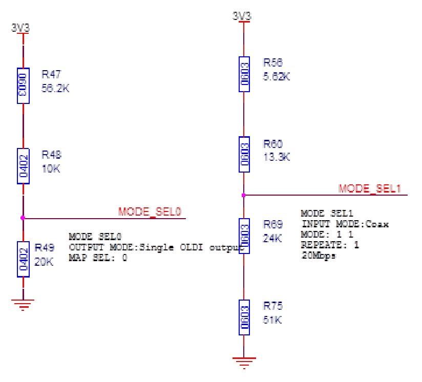
Hardware Pin Configuration:
DS90UB941:
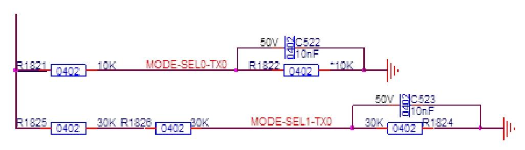
image.png

DS90UB948:

image.png

Requirements:
  1. Please analyze the possible causes of the fault based on our current fault phenomenon.
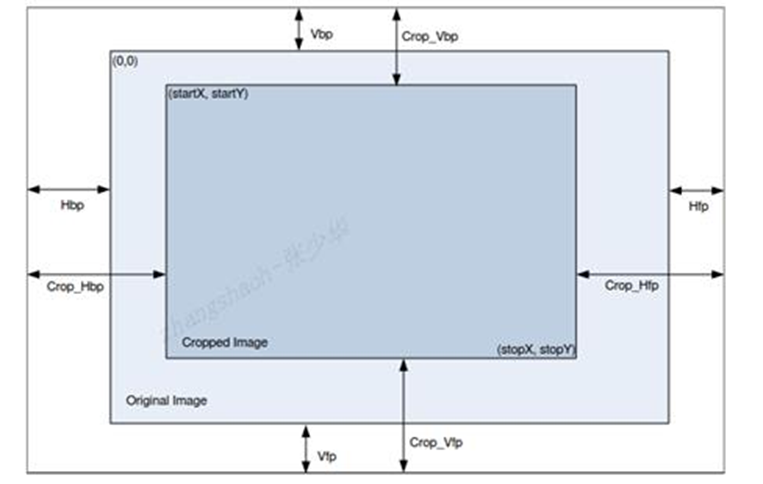
  2. Please guide us on how to adjust the parameters shown in the figure below for the DS90UB941 and DS90UB948 chips: Vbp, Hbp, Vfp, Hfp parameters. According to our current verification results, adjusting these parameters of the SOC does not result in corresponding changes to the measured LVDS signals.image.png
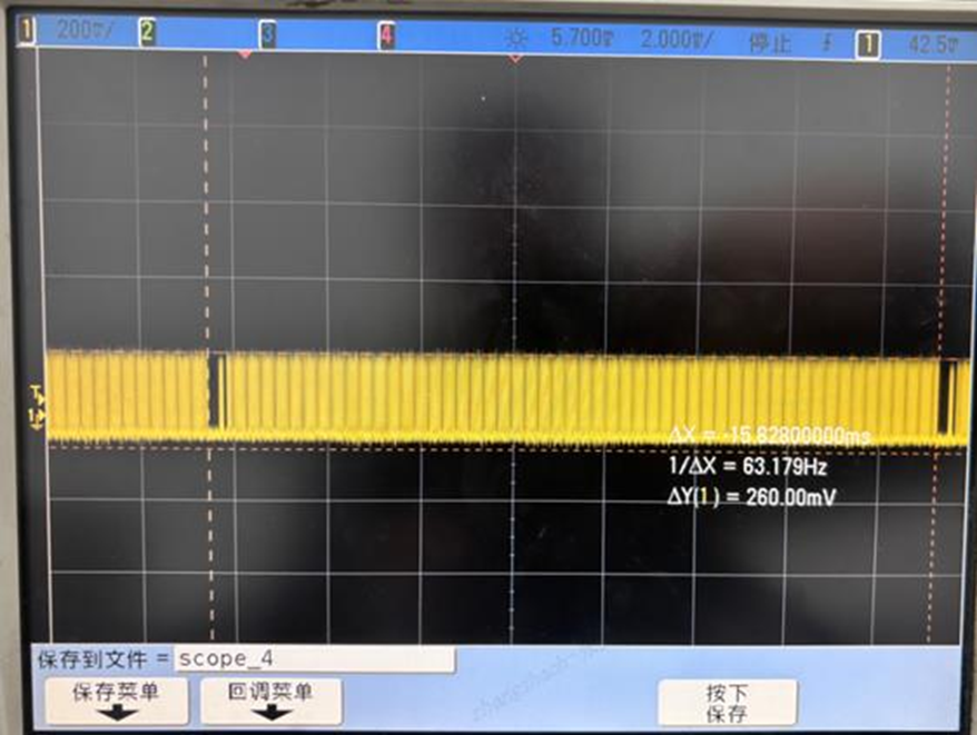
  3. The current tested LVDS signal waveform for 1 frame of data is as follows:image.png

The current tested LVDS signal waveform between two lines is as follows: (Hfp+HPW+Hbp= 8.32 us)

image.png

Power-on waveforms of VDD (yellow) and PDB (green) of the DS90UB948 chip:

image.png


  • Hi Alon,

    Happy to provide support on this matter. Who is the tier 1 and OEM?

    Please analyze the possible causes of the fault based on our current fault phenomenon.

    In order to isolate the issue, has the customer enabling PATGEN on either the SER or DES and seeing if the issue still persists? This can be achieved by using the "Pattern Generator" tab on the corresponding ALP device profiles. If the customer does not have local I2C access, let me know their full display parameters (active and blanking) and I can provide a flatlog I2C script instead. 

    Please guide us on how to adjust the parameters shown in the figure below for the DS90UB941 and DS90UB948 chips: Vbp, Hbp, Vfp, Hfp parameters. According to our current verification results, adjusting these parameters of the SOC does not result in corresponding changes to the measured LVDS

    The UB941AS and UB948 will simply pass through the incoming video timing parameters from the SoC. Nothing can be re-programmed on either the serializer or deserializer to change the blanking parameters on the FPD-Link III devices. 

    The current tested LVDS signal waveform between two lines is as follows: (Hfp+HPW+Hbp= 8.32 us)

    Where is this being measured from exactly? The UB948 output? It is difficult to tell from a screenshot alone, but the signal seems to be fluctuating. 

    Best,

    Nikolas

  • Hi Nikolas,

    Thank you for your reply.This customer is Jingyida Technology, Tier 1.The following is the customer's response.Thanks.

    In order to isolate the issue, has the customer enabling PATGEN on either the SER or DES and seeing if the issue still persists? This can be achieved by using the "Pattern Generator" tab on the corresponding ALP device profiles. If the customer does not have local I2C access, let me know their full display parameters (active and blanking) and I can provide a flatlog I2C script instead. 

    1. PATGEN mode has been verified on both the 941 and 948, and this issue does not occur.

    In order to isolate the issue, has the customer enabling PATGEN on either the SER or DES and seeing if the issue still persists? This can be achieved by using the "Pattern Generator" tab on the corresponding ALP device profiles. If the customer does not have local I2C access, let me know their full display parameters (active and blanking) and I can provide a flatlog I2C script instead. 

    2. All oscilloscope and measurement results above were obtained from the LVDS interface of the 948 output.

    Where is this being measured from exactly? The UB948 output? It is difficult to tell from a screenshot alone, but the signal seems to be fluctuating.

    3. Can you provide a reference waveform of the 948 output when the 941 and 948 are working correctly?

  • Hi Alon,

    1. PATGEN mode has been verified on both the 941 and 948, and this issue does not occur.

    Thank you for providing these bench results. This can allow us to isolate the issue to somewhere between the DSI TX of the SoC and the DSI RX of the UB941AS. With that in mind, can you please provide the customer's initialization script for the UB941AS as well as their full display timings? I'd like to confirm that their software configurations are correct.

    Best,

    Nikolas

  • Hi Nikolas,

    Thank you for your support. The customer process flow is as follows:

    ti941_i2c_write(bus_id, serial_addr, 0x01, 0x0F); // reset 941
    ti941_i2c_write(bus_id, serial_addr, 0x1e, 0x01); // enable port0
    ti941_i2c_write(bus_id, serial_addr, 0x03, 0x9a); // i2c cfg
    ti941_i2c_write(bus_id, serial_addr, 0x0e, 0x03); // GPIO1 input mode
    ti941_i2c_write(bus_id, serial_addr, 0x4f, 0x8C); // continue clock
    ti941_i2c_write(bus_id, serial_addr, 0x56, 0x00); // DSI reference clock
    ti941_i2c_write(bus_id, serial_addr, 0x02, 0x00); // lane swap

    //ESD test
    ti941_i2c_write(bus_id, serial_addr, 0x40, 0x04);//TSKIP _CNT 58.6M-0x0C 25M-0x00
    ti941_i2c_write(bus_id, serial_addr, 0x41, 0x05);//TSKIP _CNT 58.6M-0x0C 25M-0x00
    ti941_i2c_write(bus_id, serial_addr, 0x42, 0x0a);//TSKIP _CNT 58.6M-0x0C 25M-0x00

    ti941_i2c_write(bus_id, serial_addr, 0x03, 0x0A);//FILTER_ENABLE
    ti941_i2c_write(bus_id, serial_addr, 0x26, 0x02);//LINK_DETECT_TIMER
    ti941_i2c_write(bus_id, serial_addr, 0x5D, 0xC0);//FREQ_LO_THR
    ti941_i2c_write(bus_id, serial_addr, 0x5E, 0x7F);//FREQ_HI_THR
    ti941_i2c_write(bus_id, serial_addr, 0x41, 0x22);//DSI_ERR_CFG_0
    ti941_i2c_write(bus_id, serial_addr, 0x42, 0x00);
    ti941_i2c_write(bus_id, serial_addr, 0x41, 0x23);//DSI_ERR_CFG_0
    ti941_i2c_write(bus_id, serial_addr, 0x42, 0x00);
    ti941_i2c_write(bus_id, serial_addr, 0x01, 0x00); // dsi enable


    // // Set the remote device address to 941.
    //i2cset -fy 1 0x0c 0x07 0x64
    //i2cset -fy 1 0x0c 0x08 0x64
    ti941_i2c_write(bus_id, serial_addr, 0x07, (SLAVE_I2C_MCU_ADDR << 1) & 0xFE); // SLAVE_ID0
    ti941_i2c_write(bus_id, serial_addr, 0x08, (SLAVE_I2C_MCU_ADDR << 1) & 0xFE); // SLAVE_ALIAS_ID0

    ti948_i2c_write(bus_id, dev_addr, 0x26, 0x64); // SCL_HIGH_TIME
    ti948_i2c_write(bus_id, dev_addr, 0x27, 0x64); // SCL_LOW_TIME
    // ti948_i2c_write(bus_id, dev_addr, 0x29, 0x80); // vsync enable

    ti948_i2c_write(bus_id, dev_addr, 0x03, 0x78); // i2c cfg
    ti948_i2c_write(bus_id, dev_addr, 0x05, 0x1e); // i2c cfg.

    ti948_i2c_write(bus_id, dev_addr, 0x1D, 0x01); // GPIO0 Output 20250807 LCD backlight enable off (LOW)
    usleep(100 * 1000);
    ti948_i2c_write(bus_id, dev_addr, 0x1E, 0x99); // GPIO1 GPIO2 Output GPIO1 LCD screen RESET invalid (HIGH) GPIO2 LCD screen PON valid (HIGH)
    ti948_i2c_write(bus_id, dev_addr, 0x1F, 0x01); // GPIO3 Output 20250807 Alarm lights off (LOW)

    ti948_i2c_write(bus_id, dev_addr, 0x41, 0x1F);//LINK_ERROR_COUNT

    ti948_i2c_write(bus_id, dev_addr, 0x49, 0xe2); // output mode: single mode

  • Hi Alon,

    Thank you for providing this. As requested previously, can you please provide the full display timings (active and blanking)? In addition, please provide the DSI rate. This information is needed in order to verify that the register writes are correct.

    Best,

    Nikolas

  • Hi Nikolas,
    The customer's reply is as follows. Please help check it. Thank you.

    dsi datarate:352Mbit/s
    fps 45
    hact = 1280;
    hfp = 26;
    hpw = 12;
    hbp = 16;
    vact = 720;
    vfp = 8;
    vpw = 3;
    vbp = 5;

  • Hi Alon,

    Thanks for providing the additional details. Nikolas will get back to you within 1-2 Business days.

  • Hi Alon,

    Thanks for sharing those details. See below for some comments regarding their initialization script:

    • On the first line when resetting the UB941AS, all of those bits do not need to be set. Instead, 0x01 can be set equal to 0x08 (instead of 0x0F).
    • Can you confirm that the DSI TX (from the SoC) is operating in continuous clock mode?
    • The TSKIP is incorrectly calculated. Based on my calculations, the PCLK = HTOTAL * VOTAL * 45fps = 44.1MHz, which makes DSI CLK = PCLK * 12 / # of DSI lanes = 0.1323GHz, which makes TSKIP_CNT = round(65*DSI CLK-5) = 4. This means that the TSKIP register should be programmed to 0x08 and not 0x0A as currently configured.
    • The register writes detailed in Section 10.2 of the data sheet are missing. I will forward you a reference script over E2E private messaging that outlines how to incorporate these register writes.
    • HSYNC and VSYNC polarity of the DSI port are not programmed as recommended. Please refer to the aforementioned reference script via E2E private messaging for more details.

    Most notably, the TSKIP register should be re-configured for the correct TSKIP count. Let me know once the customer updates their script and if this helps.

    Also, two follow-up questions - see below:

    • What DSI operating mode is their SoC configured for (i.e. sync events, sync pulses, etc.)?
    • How many units is this affecting out of how many units total?

    Best,

    Nikolas

  • Hi Nikolas,

    Apologies for the delayed response—the customer has been occupied with other projects recently. Regarding the script you mentioned below, I haven't received it. Could you please send it to my email address: alon.chen@arrow.com?

    Thank you.

    The register writes detailed in Section 10.2 of the data sheet are missing. I will forward you a reference script over E2E private messaging that outlines how to incorporate these register writes.

    Best,

    Alon

  • Hi Alon,

    I will share the reference script for 1080p via email (note that the TSKIP and DSI configurations will need to be adjusted based on the customer's exact use case). After you are able to download the reference script, let's continue our discussions on this E2E thread.

    Best,

    Nikolas

  • Hi Nikolas,

    Thank you for your patience and support. Some issues have been resolved, but a new problem has arisen.

    When generating patterns using the internal clock, there's a very low probability that the screen will rotate, as shown in the video below.

    The following is the customer's configuration.

        serdes_err("#############TI948 start USE_PATTERN.\n");
        ti948_i2c_write(bus_id, dev_addr, 0x01, 0x01);/* RESET*/ 
        ti948_i2c_write(bus_id, dev_addr, 0x64, 0x00);/* RESET*/ 
        ti948_i2c_write(bus_id, dev_addr, 0x66, 0x1A);/* CLOCK DIVIDER M, 948 只能为 1 且无法调整。 948 的 CLK 为 140MHz*/ 
        ti948_i2c_write(bus_id, dev_addr, 0x67, 0x01);/* CLOCK DIVIDER M*/ 
        ti948_i2c_write(bus_id, dev_addr, 0x66, 0x03);/* CLOCK DIVIDER N*/ 
        ti948_i2c_write(bus_id, dev_addr, 0x67, 0x04);/* CLOCK DIVIDER N,设置为 4*/ 
        ti948_i2c_write(bus_id, dev_addr, 0x66, 0x04);/* Htotal */ 
        ti948_i2c_write(bus_id, dev_addr, 0x67, 0x36);/* Htotal*/ 
        ti948_i2c_write(bus_id, dev_addr, 0x66, 0x05);/* Htotal&Vtotal */ 
        ti948_i2c_write(bus_id, dev_addr, 0x67, 0x05);/* Htotal&Vtotal*/ 
        ti948_i2c_write(bus_id, dev_addr, 0x66, 0x06);/* Vtotal */ 
        ti948_i2c_write(bus_id, dev_addr, 0x67, 0x2E);/* Vtotal*/ 
        ti948_i2c_write(bus_id, dev_addr, 0x66, 0x07);/* Hactive&Vactive*/ 
        ti948_i2c_write(bus_id, dev_addr, 0x67, 0x00);/* Hactive&Vactive */ 
        ti948_i2c_write(bus_id, dev_addr, 0x66, 0x08);/* Hactive&Vactive */ 
        ti948_i2c_write(bus_id, dev_addr, 0x67, 0x05);/* Hactive&Vactive */ 
        ti948_i2c_write(bus_id, dev_addr, 0x66, 0x09);/* Hactive&Vactive */ 
        ti948_i2c_write(bus_id, dev_addr, 0x67, 0x2D);/* Hactive&Vactive */ 
        ti948_i2c_write(bus_id, dev_addr, 0x66, 0x0A);/* HSYNC */ 
        ti948_i2c_write(bus_id, dev_addr, 0x67, 0x0C);/* HSYNC*/ 
        ti948_i2c_write(bus_id, dev_addr, 0x66, 0x0B);/* VSYNC */ 
        ti948_i2c_write(bus_id, dev_addr, 0x67, 0x03);/* VSYNC*/ 
        ti948_i2c_write(bus_id, dev_addr, 0x66, 0x0C);/* HBP */ 
        ti948_i2c_write(bus_id, dev_addr, 0x67, 0x10);/* HBP */ 
        ti948_i2c_write(bus_id, dev_addr, 0x66, 0x0D);/* VBP */ 
        ti948_i2c_write(bus_id, dev_addr, 0x67, 0x05);/* VBP*/ 
        ti948_i2c_write(bus_id, dev_addr, 0x66, 0x0E);/* Polarity */ 
        ti948_i2c_write(bus_id, dev_addr, 0x67, 0x03);/* Polarity*/ 
        ti948_i2c_write(bus_id, dev_addr, 0x65, 0x04);/* clock source & timing source */
        
        ti948_i2c_write(bus_id, dev_addr, 0x1D, 0x09); // GPIO0 Output 20250807 LCD背光使能关闭(LOW)
        ti948_i2c_write(bus_id, dev_addr, 0x1E, 0x99); // GPIO1 GPIO2 Output GPIO1 LCD屏RESET无效(HIGH) GPIO2 LCD屏PON有效(HIGH)
        ti948_i2c_write(bus_id, dev_addr, 0x1F, 0x01); // GPIO3 Output 20250807 报警灯关闭(LOW)
        ti948_i2c_write(bus_id, dev_addr, 0x49, 0xe2); 
    
        ti948_i2c_write(bus_id, (0x0c << 1), 0x70, (0x38 << 1)); // i2c forwarding
        ti948_i2c_write(bus_id, (0x0c << 1), 0x77, (0x38 << 1)); // i2c forwarding
        
        lcd_driver_i2c_write();// Turn on the LCD backlight
        ti948_i2c_write(bus_id, dev_addr, 0x64, 0x95);/* enable PATTERN MODE*/ 
        serdes_err("#############TI948 end USE_PATTERN.\n");

    Best,

    Alon

  • Hi Alon,

    Thank you for your patience and support. Some issues have been resolved,

    Glad to hear there has been some progress. Can you clarify on what specifically has been resolved just so I can better understand where this bring-up stands?

    When generating patterns using the internal clock, there's a very low probability that the screen will rotate, as shown in the video below.

    Can you provide some more details regarding the reproduction method and any possible recovery methods? See below for some questions related to that:

    1. How many systems is this impacting? Out of how many total?
    2. How many ICs is this impacting? Out of how many total? Any ABA swaps performed?
    3. Is there any way to recover this phenomenon? For example, does the DES soft reset recover the flip?
    4. What is exact power-up sequencing being followed? With respect to the SER, DES, and TCON?

    Best,

    Nikolas

  • Hi  Nikolas,,

    Thank you for your support.

    Glad to hear there has been some progress. Can you clarify on what specifically has been resolved just so I can better understand where this bring-up stands?

    I'm very sorry, I misunderstood the customer's feedback, leading to a communication error. I confirmed with the customer again that they tried the script you sent in the email, but the screen noise issue persists.

    • How many systems is this impacting? Out of how many total?
    • How many ICs is this impacting? Out of how many total? Any ABA swaps performed?
    • Is there any way to recover this phenomenon? For example, does the DES soft reset recover the flip?
    • What is exact power-up sequencing being followed? With respect to the SER, DES, and TCON?

    The customer is currently confirming these questions and information. We will get back to you later.

    Thanks again.

    Alon

  • Hi Alon,

    I'm very sorry, I misunderstood the customer's feedback, leading to a communication error. I confirmed with the customer again that they tried the script you sent in the email, but the screen noise issue persists.

    The script attached in the email was just a reference. Did they update the script based on their DSI configurations as requested (i.e. TSKIP, DSI parameters, etc.)?

    If possible, please attach the exact script they ran where the issue persisted.

    The customer is currently confirming these questions and information. We will get back to you later.

    Understood - looking forward to your feedback.

    Best,

    Nikolas

  • Hi Nikolas,

    We are very grateful for the customer feedback that they configured the script according to the email you sent, but there was no improvement. The customer saw a passage in ZHCAEW4 stating, "Timing issue: Usually, the individual timings of the serializer and deserializer can be met, but the power-on timing between them is easily overlooked. The deserializer needs to wait for the serializer to have a stable output before it can pull up PDB."

    Could you please explain what "waiting for the serializer to have a stable output" specifically refers to? How can the deserializer determine the stability of the serializer?

    Thank you.

    Best,

    Alon

  • Hi Alon,

    The customer saw a passage in ZHCAEW4 stating, "Timing issue: Usually, the individual timings of the serializer and deserializer can be met, but the power-on timing between them is easily overlooked. The deserializer needs to wait for the serializer to have a stable output before it can pull up PDB."

    I am not familiar with ZHCAEW4 and cannot follow it given it is not in English. The verbiage does seem a little lax, but the requirement is correct in that the DES should not be powered on until the SER begins transmitting valid video data. See my response below for more details.

    Could you please explain what "waiting for the serializer to have a stable output" specifically refers to? How can the deserializer determine the stability of the serializer?

    For more details on this front, please refer to the deserializer device datasheet. More specifically, the deserializer should be powered on after the serializer starts sending valid video data. See the following from the datasheet:

    Best,

    Nikolas

  • Hi Nikolas,

    Thank you for your patience in addressing these questions.

    1. Can SER be configured alone to output valid video stream data when DES is not powered on, with DES configured correctly afterward?

    2. The customer has provided the following video showing snowy noise. Has your company encountered this issue before? Do you have any troubleshooting suggestions? Thank you.

    Best,

    Alon

  • Hi Alon,

    1. Can SER be configured alone to output valid video stream data when DES is not powered on, with DES configured correctly afterward?

    Yes, this is acceptable.

    2. The customer has provided the following video showing snowy noise. Has your company encountered this issue before? Do you have any troubleshooting suggestions? Thank you.

    A snow screen like this can be attributed to a variety of sources. To investigate this further, I'll need feedback on the question I asked previously on Feb 05. I am copy and pasting them below for your convenience and adding a few additional questions for debugging purposes.

    • How many systems is this impacting? Out of how many total?
    • How many ICs is this impacting? Out of how many total? Any ABA swaps performed?
    • Is there any way to recover this phenomenon? For example, does the DES soft reset recover the flip?
    • What is exact power-up sequencing being followed? With respect to the SER, DES, and TCON?
    • Has SER PATGEN been tried? Or DES-only PATGEN been tried? And does the issue persist with either?

    Best,

    Nikolas

  • Hi Nikolas,

    The customer has resolved this issue, which was caused by a timing problem. Thank you for your continued patience and support.

    Best,

    Alon