TCAN1051HV-Q1: Interface issue with TCAN332

Part Number: TCAN1051HV-Q1
Other Parts Discussed in Thread: TCAN332, TCAN1051HV

Hi,

We are facing an issue with the Interface of TCAN1051HV and TCAN332 on the single CAN bus.

Detailed issue is as follows.

We have three modules namely A,B and C connected on a single CAN bus where Module A,B are having TCAN1051HV (operated on 5V bus side and 3.3V on IO side) and Module C is having TCAN332 (operated on single 3.3V). CAN bus operating speed is 1mbps.

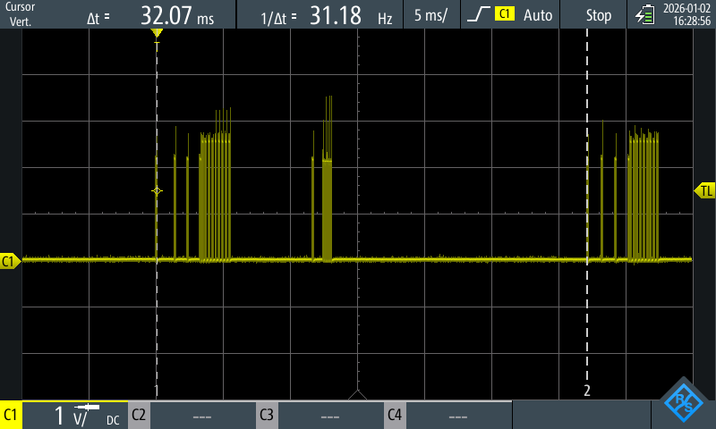
In normal mode of operation i.e all the modules LV power is enabled but HV power is disabled, there are no communication issues on the bus and also signal on the bus looks clear (attached image 1).

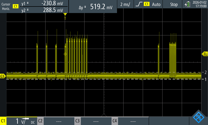
In HV power enabled case, the communication is getting failed and signal also completely noisy and observed missing frames from all the 3 Modules. (attached image2)

Then I have changed the CAN device to TCAN1051HV in Module C (using some jumpers in 1 Module C changed TCAN332 to TCAN1051HV - But solution not possible in next units) and observed clean CAN bus signal in LV and HV power enabled cases also. (attached image 3)

Are the TCAN1051HV and TCAN332 not capable to work on a single CAN bus because of the voltage differences? Image1.pngd71f9e61-1393-4f7a-b2f2-4affe9ac69e3.pngImage 3.png

  • Hi Venkata,

    They can both work if within their recommended voltage levels. However, unsure what signal you are showing and suspect the power supply.

    If so, would recommend to probe each device's power supply pins to measure their actual voltage levels during the observations as I suspect the 3.3 V device's supply becomes too unstable from the noise while the 5 V device has more room during the unstable duration. May also ensure sufficient decoupling capacitors are included and as close to each power supply pin as much as possible, thanks.

    Best Regards,

    Michael.

  • Dear Michael,

    However, unsure what signal you are showing

    All waveforms are captured on CANH, CANL lines in different cases

    Image1: LV supply is ON and HV supply is OFF. Module A,B - TCAN1051HV , Module C - TCAN332.

    Image2: LV and HV supply is ON. Module A,B - TCAN1051HV , Module C - TCAN332.

    Image3: LV and HV supply is ON. Module A,B,C - TCAN1051HV. (Module C, CAN transceiver is replaced with TCAN1051HV)

    If so, would recommend to probe each device's power supply pins to measure their actual voltage levels during the observations as I suspect the 3.3 V device's supply becomes too unstable from the noise while the 5 V device has more room during the unstable duration

    We have measured the supply voltages while LV and HV supply is ON, and found the voltages are 3.3 and 5V. and the decoupling capacitors are used as per the transceiver datasheets.

    is there any other possible reasons that could effect the CAN communication when two different transceivers(TCAN1051HV and TCAN332) are used on the same bus?

    Best Regards,

    Nagaraju.

  • Hi Nagaraju,

    Thanks for clarifying. If feasible, please share TXD / RXD / CANH / CANL failing and passing waveforms as they can share the same CAN bus if the bus voltages (common mode) stays within what both devices tolerate. Hence, module C's / the bus local reference is most likely seeing common mode shifts / faults when HV is enabled.

    Hence, confirm if HV enabled causes CANH / CANL to go beyond the 12 V common mode spec, relative to module C's GND as this may cause misbehavior (dominant stuck, RXD corruption etc) I.e., the 3.3 V device seems to specify up to 12 V while the 5 V device specifies up to 30 V.

    Would recommend probing each module's GND if any GND offsets.

    May also scope the VCM when HV enabled to help double confirm if beyond ± 12 V is observed:

    • I.e., CANH + CANL relative to module C's GND.
    • CANH to GND and CANL to GND at module C, thanks.

    Best Regards,

    Michael.