This thread has been locked.

If you have a related question, please click the "Ask a related question" button in the top right corner. The newly created question will be automatically linked to this question.

DS320PR810: Decoupling and stitching capacitators near the VCC pins

Part Number: DS320PR810
Other Parts Discussed in Thread: DS320PR410

Hello,

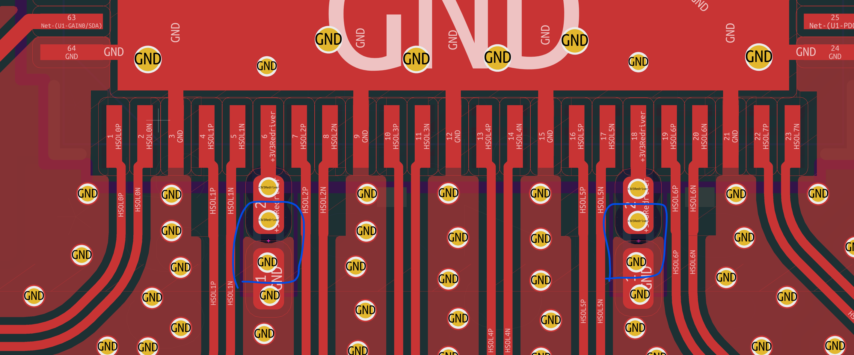
I was looking at my design, and I noticed that the VCC pins and a bit of the trace for it are close to the actual differential pairs that go into the DS320pr810 redriver. Being so close to them, the VCC pin and traces can be considered one of the reference plane to the differential pairs, so it should be stitched together using some capacitators to the rest of the reference planes.

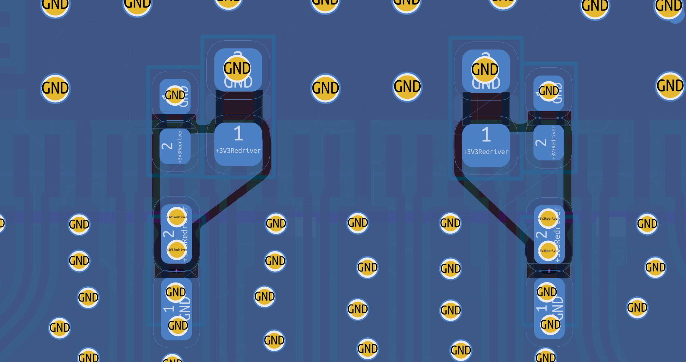
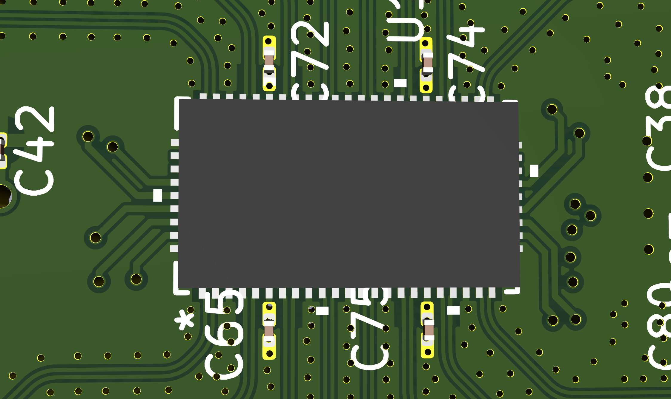
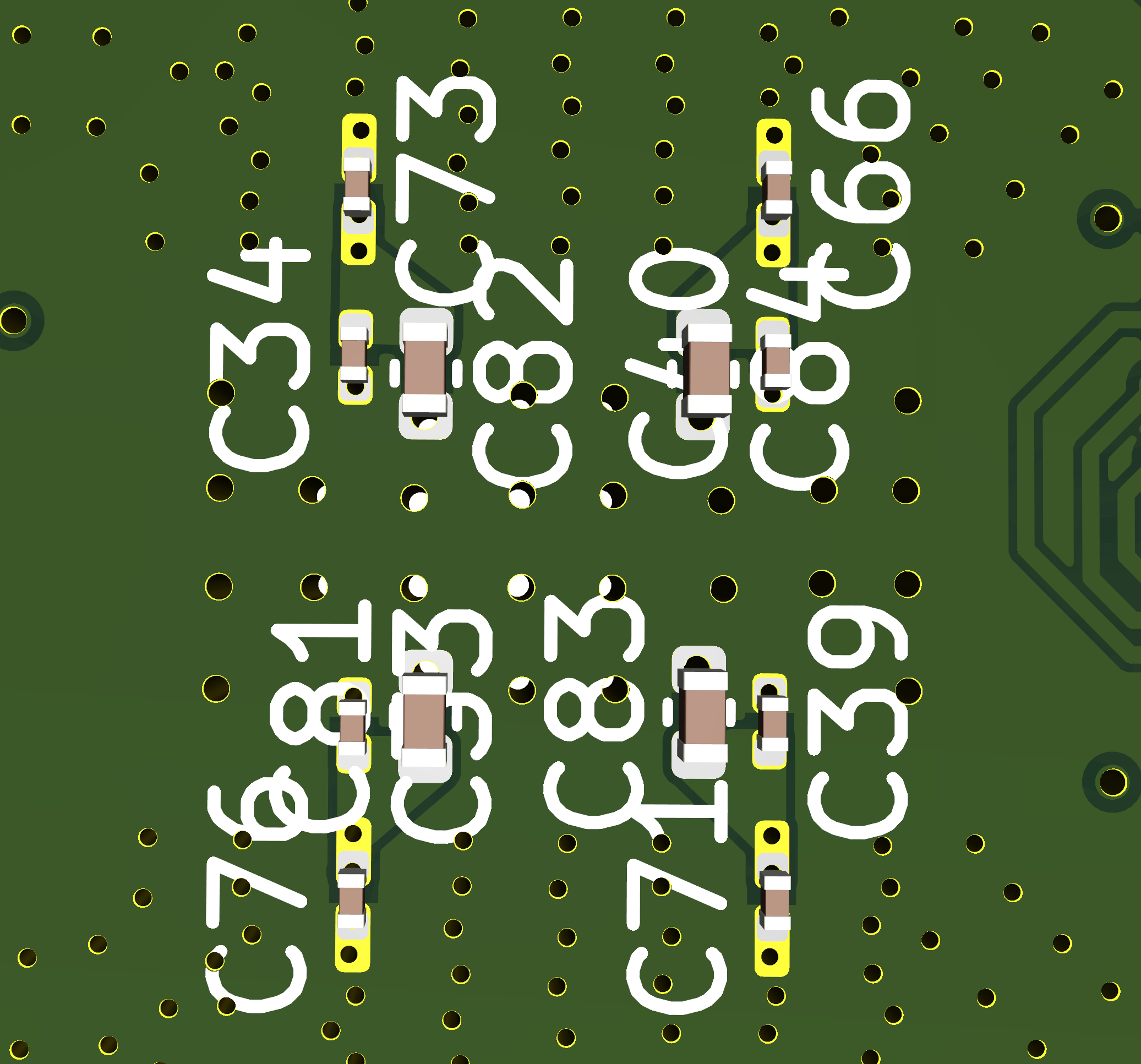
So I added some stitching capacitators on the front and back of the VCC pins and traces like in the images bellow:

image.png

image.png

image.png

image.png

I noticed that in one of your reference designs for another redriver you added a similar layout, for the ds320pr410 evaluation board but for the evaluation board of the DS320PR810 redriver, these capacitators are missing. So what will be the best approach for this? Can the additional capacitators reduce crosstalk, even if it by a very small margin or will they only make things worse?

  • Hi Andrei,

    The purpose of C143 and C144 (and all decoupling capacitors placed on the same plane as DS320PR410 device) in DS320PR410EVM is for power supply decoupling. Due to constraints in the layout on the bottom side of the PCBA, C143 and C144 were moved to the top side.


    Please follow the approach shown in DS320PR810EVM and DS320PR810 datasheet. Place decoupling capacitors close to VCC pins and directly under the device if possible. 

    Best,

    Charles

  • I already added decoupling capacitators on the bottom side too, 3 in total, 2 of them face towards the pad of the redriver and have vias directly in their pad connecting to the redriver pad:

    And one faces opposite of the pad.

    I guess I should remove all other capacitators that are further away from the pad of the redriver if they do more harm than good.

  • I think there are 2 different roles the capacitators are filling here. The ones that follow along the path of the pcie traces are bypass capacitators, allowing the return current and noise generated by the nearby pcie trace to leave the VCC rail as early as possible so that the redriver gets a more clean input voltage.

    The capacitators between the groud pad of the redriver and the VCC pins are the decoupling capacitators, making sure that when the redriver needs more power, the voltage stays stable by acting as a reservoir for sudden power deman spikes.

    Also, I am not too sure that what you said is correct, there is still enough room on the bottom side of the redriver DS320410 to add the additional capacitators if needed 

  • Hi Andrei, 


    I understand your concerns of the PCIe trace causing noise on the VCC rail. We have not seen this issue while testing DS320PR410 and DS320PR810 EVMs.

    If supply noise is a concern, I recommend running simulations to verify that VCC noise remains within the recommended supply noise tolerance specified on page 7 of the DS320PR810 datasheet.

    Best,
    Charles