This thread has been locked.

If you have a related question, please click the "Ask a related question" button in the top right corner. The newly created question will be automatically linked to this question.

TUSB2E11: USB Not Recommended Pre-Emphasis Settings

Part Number: TUSB2E11

Hi expert,

My customer has some questions about TUSB2E11 (relatively urgent):

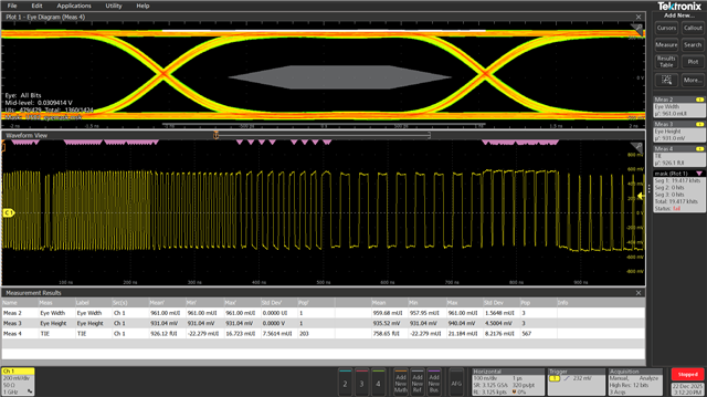
The channel that this repeater is driving is very lossy. We've had to tune the USB PHY TX settings significantly in order to pass the eye mask. However, since the test points we can probe are not exactly at the RX pins, we want to have more margin in our measurement. The current tuned TX settings are already maxed out, so the only setting we still have available to tune are the not recommended pre-emphasis settings. What is the concern with using these settings? Between the below screenshots, the only change is the pre-emphasis amount being 0x5 vs 0x7. Slew rate is 425ps, amplitude is 1040mV, and pre-emphasis amount is at 0.65UI.


Thank you!

McKenna

  • Hi McKenna,

    Looks like only one picture sent, the one I can see looks like there is decent margin. Is this the one with pre-emphasis set to 0x7?

    I've asked internally to see why higher settings are not recommended, and will feedback what I hear.

    What is the loss between the host and the repeater, and the repeater and the device? Any cable lengths? A block diagram of the system would help to understand as well.

    What is the value of E_EQ_P1? Are these being adjusted at all? Does adjusting this cause any noticeable difference in the eye diagram?

    Looks like there are using the max value for their TX amplitude as well. Does the customer system function fine with these settings? What is U_DISCONNECT_THRESHOLD set to?

    Thanks,

    Ryan

  • Hi Ryan,

    Thanks for the quick turnaround! Not sure why both didn't make it, attached both below:

  • Hi McKenna,

    Is this for a host or device mode setup?

    The reason these settings are not recommended is because these settings can cause the Host Disconnect Threshold to degrade. In our experience, if this must pre-emphasis is needed, it's likely that there are issues in the design.

    A block diagram with lengths/loss would be good, schematic or layout for review would not be bad as well.

    Thanks,

    Ryan

  • Hi Ryan,

    Thanks for the feedback, I'll work on getting those answers for you. 

    Here is some more feedback from customer:

    I have not yet probed between the host and the repeater, but I will try and get that today.

    The below scope shots show the impact of the channel. The scope measures the eye height at the middle of the UI rather than at the narrowest point, but my estimation around the mask crossover point is about a -8.2dB loss. This is across a 1.3m cable with 9 connector discontinuities, an OVP chip, and a mux before the signal reaches the RX pins. I will work on a block diagram for you.

    For the screenshots I sent, E_EQ_P1 is at its default setting of 0.34dB, but I did find that tuning it opened up the eye slightly. I had tested with 0x8 (2.69dB) but will play around with it more today. I have not tried tuning the other eUSB RX settings. Without the tuned settings, we are seeing device disconnects over this interface. I don't think we've had enough time with the new settings to characterize the device behavior beyond checking the eye diagram. We have not adjusted the disconnect threshold so it's at 0x8 for 685mV. Do you recommend increasing this when increasing the amplitude?


    Thank you!

    McKenna

  • Hi McKenna,

    If they are increasing the TX amplitude, I would also recommend increasing the disconnect threshold, yes. The GPIO settings of the TUSB2E11 increase the disconnect threshold as well when the TX amplitude is increased.

    They said they aren't probing at the DP/DM pins of the device, is there any way they can probe there or at the connector?

    If they have 9 connectors in the signal path as well as a 1.3 meter cable, I could definitely see how that would degrade the signal integrity a good bit.

    If this is a host mode application, I.E the host is an eUSB host, then adjusting disconnect threshold could help with intermittent disconnects if the disconnect threshold is what's causing the issue. However, I would still advise against using the not recommended PE settings.

    Thanks,

    Ryan

  • Hi Ryan,

    Thank you for all the information on the pre-emphasis limits. Customer will let their SW team know not to exceed the recommended values. Assuming they're using the maximum recommended PE and amplitude, do you have a disconnect threshold that you'd recommend as a starting point? These disconnect failures sometimes take a while to manifest so it would be helpful to know where to start.

    This is only for the host setup. Currently they don't have a way to reliably send traffic for device mode. Their SW team is working on a way to send this traffic so they can check the other direction as well. They can show us sections of schematics for the repeaters and muxes, but they don't think seeing all the files will be very helpful since there are so many boards to trace the signal through.

    They created a block diagram to show the entire signal path and the DP/DM trace lengths between each discontinuity. Hopefully this helps paint a better picture of the system. They miscounted the connectors, and there are actually "only" 8. They are planning on removing the OVP chip for future builds, which has shown to degrade the signal integrity. Unfortunately, there may not be much else we can change at a system level. The diagram also shows where they are able to probe. It's very difficult to probe anywhere else in the path, but these test points capture the bulk of the discontinuities as well as the long cable.

    Thank you!

    McKenna

  • Hi McKenna,

    Per what we talked about in the meeting, please look at adjusting the disconnect threshold while keeping pre-emphasis outside of that not-recommended range. Additionally, implementing a redriver if possible might help to reduce the settings needed from the PHY while ensuring the signal still passes the eye mask.

    Thanks,

    Ryan

  • Hi Ryan,

    Thanks a ton for your help! I was wondering if you could provide TX and RX IBIS-AMI models for the TUSB2E11?

    Thank you!

    McKenna

  • Hi McKenna,

    Please accept my E2E friend request, and I can send our model over.

    Thanks,

    Ryan

  • Hi Ryan,

    Just accepted, thanks!

    McKenna

  • Hi McKenna,

    Responded over E2E PM.

    Thanks,

    Ryan

  • Hello,

    Closing thread due to inactivity. If you have any follow-up questions or concerns, feel free to reply.

    Thanks,

    Ryan

  • Hi Ryan,

    Thanks for your help here! A couple follow up questions:

    Does the standard USB2 RX sensitivity mask also to the repeater? I saw the datasheet mentions the squelch threshold, but not a required eye width. Does that mean the 35% to 65% UI width doesn't apply? We are probing close to the USB pins and using this mask as a performance metric, but if there is a more accurate way to gauge performance that would be very helpful. Maybe we could probe on the eUSB side and compare that against an eUSB TX spec instead. Please let me know your thoughts!


    Thank you!

    McKenna

  • Hi McKenna,

    Section 7.1.5 of the eUSB2 spec has eye diagram templates for the eUSB2 side of the repeater. I would recommend using that to determine where each test point is, and what the expected eye mask is. 

    I saw the datasheet mentions the squelch threshold, but not a required eye width. Does that mean the 35% to 65% UI width doesn't apply?

    What do you mean by doesn't apply? From the 35% to 65% width, the eye diagram should not violate this mask.

    For RX Sensitivity, I'm not sure these eye masks apply.

    Thanks,

    Ryan

  • Hi Ryan,

    Thanks for the feedback. One more follow up question:

    If we set the USB squelch detection threshold to 0x7 (minimum squelch voltage), what do the squelch/no squelch voltages become?


    Thanks,

    mcKenna

  • Hi McKenna,

    The minimum squelch voltage should be 85mv.:

    Section 11.2 of the TUSB2E11 datasheet has some guidelines for these settings, if that helps at all.

    Thanks,

    Ryan

  • Hi Ryan,

    I understand the minimum level, but should the voltage required for leaving  the squelch state decrease below 150mV when the minimum is set to 85mV? Or does that setting only change the minimum value?

    Thanks,

    McKenna

  • Hi McKenna,

    I'm not sure what the customer means by "leaving the squelch state." Setting the minimum to 85mV means that the USB2 side of the repeater will not squelch any signal with a voltage greater than 85mV, and should exit any squelch state at that point.

    Thanks,

    Ryan

  • Hi Ryan,

    My understanding was that once the squelch state is entered (voltage <100mV usually), then it has to return to above 150mV to leave the squelch state and be considered valid data. Is that not the case? The wording in the spec doesn't really discuss what happens between those voltage levels, so I may be misunderstanding here.

    Since the max threshold in the datasheet seems to track the minimum threshold, I figured that lowering the minimum threshold would mean that data would become valid again once the voltage goes above 120mV or so. 

    Please let me know if I'm misunderstanding something here. For now I will proceed with the 150mV or template 4/6 values. My initial question was aimed at trying to understand if the repeater thresholds were different than the standard templates. 

    Thank you!

    McKenna

  • Hi McKenna,

    My understanding was that once the squelch state is entered (voltage <100mV usually), then it has to return to above 150mV to leave the squelch state and be considered valid data. Is that not the case? The wording in the spec doesn't really discuss what happens between those voltage levels, so I may be misunderstanding here.

    Adjusting this register would cause the repeater to enter the squelch state with any voltage less than 85mV at the lowest setting. Typically though yes, per the spec it is around 100mV. The register allows the customer to adjust this threshold and go out of spec.

    Thanks,

    Ryan

  • Hello,

    Closing thread due to inactivity. If you have any follow-up questions or concerns, feel free to reply.

    Thanks,

    Ryan