This thread has been locked.

If you have a related question, please click the "Ask a related question" button in the top right corner. The newly created question will be automatically linked to this question.

TIC12400-Q1: How long can registers be read stable after initialization

Part Number: TIC12400-Q1

Hi Expert,

My customers found that after initialization of the TIC12400-Q1 , the read data of register is not stable until after some delay (around 1ms). So customers want to ask:

Do we have such requirements to read the registers data after the initialization and configuration of the registers?

If not, any other possible reasons for this issue? (MCU & Vcc of this device is fully on)

BR,

Manu

  • Hello Manu,

    What does the customer mean when they say "read data of register is not stable" ? After they initialize the part (configure all registers and Trigger bit = 1), the customer reads the register twice and capture different values? 

    Is this running in continuous or polling mode?

    Regards,

    Josh

  • Hi Josh,

    Thanks for reply. Customer is in polling mode and POLL_TIME is set to be 4ms. Customers sequence is to initiate the device --> configuration registers --> write trigger bit =1 --> read the registers.

    So is this relevant to the polling mode and POLL_TIME?

    BR,

    Manu 

  • Hello Manu,

    This might be related to the polling time the customer has configured. 

    Polling time means the TIC12400-Q1 will cycle through all enabled INx inputs in a 4ms window. At the end of the polling time, the part will start the sequence again.

    The TIC12400-Q1 will store input values once per polling time. Most likely this is what the customer is observing and no "instability" is occurring.

    Regards,

    Josh

  • Hi Josh,

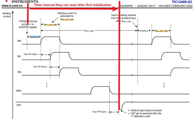
    Understood and thanks for the detailed explanation. While customers still want to know when exactly they can read all the status of input after initialization and the trigger bit set to 1. Namely the want to know the if they can calculate an accurate time of the red interval marked below. Because waiting for a whole polling time is too long and the INT pin they are not using them so they cannot detect them either.

    For example, if they use all channels as ADC mode, will the first interval calculated as the Tstartup+23*TADC+TPOLL_ACT_TIME+1*TADC=Tstartup+24*TADC+TPOLL_ACT_TIME? (Calculated this according to the time block below)

    BR,

    Manu

  • Hello Manu,

    Regardless if you have all channels enabled or only one, your sequence will follow: Tstartup + TPOLL_TIME. After the first initialization (Trigger 1) the sequence will follow: TPOLL_TIME.

    The switch status of each input will be stored in registers ANA_STAT0 to ANA_STAT11 (in ADC mode) within the TPOLL_ACT_TIME period.

    Regards,

    Josh

  • Hi Josh,

    Understood that the TPOLL_TIME is the longest buffer that they can read all the status. While this time is too long for customers even though they set it up as 2ms after the initialization after start up. So they want to know the shortest time terminal between the trigger set to 1 till they can successfully read all the input status.

    As datasheet showed, it should be Tstartup+24*TADC+TPOLL_ACT_TIME if all the inputs are in ADC mode. If we add some buffer, would it be the (Tstartup+24*TADC+TPOLL_ACT_TIME)*1.5 for the shortest time the can read all the input status? Pls let me know if we can provide an equation for providing the shortest time interval between the trigger bit set to 1 till all status can be read.

    BR,

    Manu

  • Hello Manu,

    The TADC time is part of the TPOLL_ACT_TIME. The ADC won't start reading the inputs without the wetting currents turning on first.

    If we look at it from TPOLL_ACT_TIME view, the formula would be Tstartup + 24* TPOLL_ACT_TIME. After the first sequence, it will only be 24*TPOLL_ACT_TIME.

    If we set TPOLL_ACT_TIME to the lowest value (64us), it would take ~1.5ms to read all 24 inputs.

    Regards,

    Josh