DS90UB928Q-Q1: LVDS to RGB interface for Second Display

Part Number: DS90UB928Q-Q1
Other Parts Discussed in Thread: DS90UB928Q, DS90CR286AT-Q1

Hello,

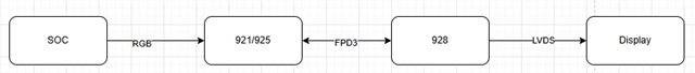
I am using DS90UB927Q and DS90UB928Q pair for our second display of our HMI project.

So for this project we may use RGB interface Displays also.

So i found DS90CR286AT-Q1 IC for that purpose. But I have question about obtain all circuit in one PCB.

Can I make some kind of variant that both includes RGB and LVDS with using single DS90UB928Q?

Is the PCB layout could be make reliable, and how can I make it?

Is there option for FPD-link serdes which one side shall be RGB and one side is LVDS?

Best regards,

Egemen

  • Hi Egemen,

    Happy to help. 

    Can I make some kind of variant that both includes RGB and LVDS with using single DS90UB928Q?

    The DS90UB928Q is just used for LVDS output. The DS90UB926 can be used for RGB output. 

    The  DS90CR286AT-Q1 can be used as a standalone LVDS - RGB converter if it matches your use case (in PCLK range, don't need FPD-Link cable for distance between LVDS source and RGB display). 

    Is the PCB layout could be make reliable, and how can I make it?

    We have PCB layout recommendations listed at the bottom of our datasheets for all our devices to help with your design. We can also do schematic and layout reviews (just post on E2E forum) once you have your design.

    Is there option for FPD-link serdes which one side shall be RGB and one side is LVDS?

    Yes, the DS90UB921/925 can be used as RGB serializer and the 928 can be used as a LVDS deserializer. Something like this:

    BR,

    Esther

  • Hello Esther,

    Thank you for your reply.

    So according to your answers can I apply something like this?

    Best regards,

    Egemen

  • Hello,

    Additionally since we have two variant for displays (one for LVDS displays and other for RGB) in single PCB, and since the case I can use DS90UB928Q for LVDS and DS90UB926Q for RGB (SOC side shall be LVDS to FPD link for both cases), how can we make the layout for FPD to prevent stubs? Can I use 0R resistor to prevent stub or dos this also breaks the signal integrity?

    Best regards,

  • Hi Egemen,

    Your block diagram is correct.

    For your second question, I would suggest a tripad on the AC coupling capacitors. 

    BR,

    Esther