This thread has been locked.

If you have a related question, please click the "Ask a related question" button in the top right corner. The newly created question will be automatically linked to this question.

TUSB319-Q1: TUSB319-Q1 Google Phone Charger Issue

Part Number: TUSB319-Q1
Other Parts Discussed in Thread: TUSB320, TUSB320EVM, TUSB319EVM

Hi team,

Customer found the Google Charger power off/start fail.

We take this E2E for discusstion.

               Google Pixel 10

Inactive Detach/ Reverse Attach

PASS

PASS

(USB-Type-C at UUT)

PASS

PASS

Turn OFF/ ON Display

PASS

PASS

Restart

PASS

PASS

Power Off/ Start

FAIL

FAIL

Thanks

Xiaoxiang

  • Hi Xiaoxiang,

    Thanks for posting this E2E. Like you said, if the customer can confirm the voltage on the CC pins during a successful and when powered-off, I would appreciate it. We essentially want to capture three states: Initial Connection (When it is successful), the pins during TUSB319-Q1 reset, and the pins after the TUSB319-Q1 comes out of reset.

    Ideally, the CC pins are pulled-down during a successful connection. During reset, if there is no power to the TUSB319-Q1, the CC pins should not be pulled up.

    Additionally, can the customer monitor the ID pin to see what the status is during power-on, reset, and after reset?

    Thanks,

    Ryan

  • Hi Yvonne,

    Would it be possible to also monitor the ID pin of the TUSB319-Q1 during testing? This pin is a good indicator of whether a type-C connection has been made. If the ID pin is pulled-down, the TUSB319-Q1 sees an active type-C connection. If the ID pin is high, then the TUSB319-Q1 does not see a connection.

    E-marker cables are used primarily for Power Delivery (PD) functionality. The TUSB319-Q1 does not support PD functionality or VCONN functionality.

    Where are the CC pins being measured? On the Pixel 10, or at the type-C connector of the silver box?

    Looking at the waveforms provided, it looks like a connection is not being made over the CC pins when the silver box is powered on after being restarted. Additionally, it looks like the Pixel 10 may be trying to configure as a DFP. This could be an issue, as the TUSB319-Q1 will also try to configure as a DFP :

    The red line from slide 6, CC2, stays high before and after the silver box is enabled, indicating that no connection is made. Additionally, CC2 staying consistently high indicated that the Pixel 10 is trying to configure as a DFP.

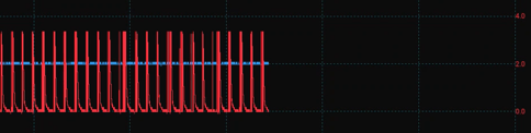
    If you look at the waveform for an IPhone with the silver box off, you can see that the IPhone is toggling CC2 high and low constantly. This indicates that the IPhone is configured as a DRP, and can configure as a UFP or DFP. Since the TUSB319-Q1 is DFP, the IPhone likely configures as a UFP, and the connection is made. My suspicion is that the Pixel is having a hard time making a connection due to the CC controllers on both devices trying to configure as a DFP.

    If you have just the silver box on with no phone connected, one of the CC lines should be pulled up similar to how the Pixel10 pulls the CC line up.

    If possible, I would like to see the CC pins with just the silver box connected, as well as flipping the type-C cable to ensure the CC pins are being pulled-up as expected in both orientations. Additionally, seeing the CC pins with a non-EMarker cable would be good as well to see what the difference between the two cables is. And again, please monitor the ID pin if possible.

    Thanks,

    Ryan

  • Hi Ryan,

    The CC pins were measured on a breakout board between the USB hub output port and cable connected to the phone. 

    I have emailed you the requested waveforms.

    Is the use of an E-marker cable mandatory when conducting the Type C-Interoperability test for USB IF Certification? 

    Thanks,

    Yvonne

  • Hi Yvonne,

    Our team is out today on US holiday. Please expect a response on 1/20 after the holiday.

    Thanks,

    Ryan

  • Hi Yvonne,

    Thank you for gathering those waveforms. It does look like there is some difference in terms of the CC pin waveforms going between the IPhone and the Pixel10:

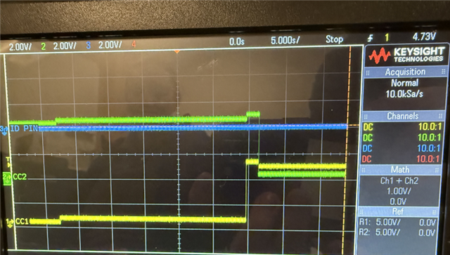
    With an IPhone, you can see that before the silver box is powered, the CC1 pin is toggling. This is likely because the IPhone is configured as a DRP, and since there is no connection, the CC pins are toggling high and low. Then, once the silver box is powered on, you see the ID pin go high for a short time before going low. This shows that the TUSB320 is powering on, seeing the connection with the Pixel10 and beginning the CC negotiation process over the CC pins, with the ID pin going low indicating its successful connection.

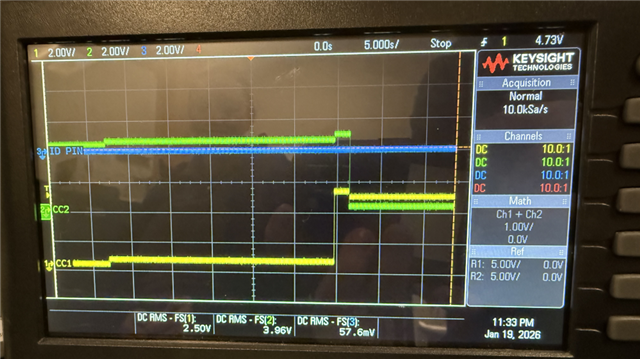
    With the Pixel10 in the same scenario, however, you can see that CC2 is pulled high even before the silver box is powered, as opposed to the IPhone scenario where one of the CC pins is toggling high and low looking for a connection. And even once powered on, the ID pin does not toggle high and stays low the entire time, which makes me wonder if the EMarker voltage could potentially be causing issues with the CC negotiation process, especially since it looks like the Pixel10 is trying to configure as a DFP.

    However, once you switch to the non E-Marker cable, the performance looks about as expected, with the CC pin toggling high and low as expected from a phone's type-C port. This leads me to believe that the EMarker cable is the main cause of the issue here, interfering in the CC negotiation process. Would it be possible to try other EMarker cables and see if these also act the same?

    I have reached out to see if EMarker capabilities are required for non-PD systems, as EMarkers are usually only used for PD functionality, which is not being used here. My understanding is that if VCONN or PD functionality are not being used, then an EMarker is not needed, but I will let you know.

    Thanks,

    Ryan

  • Hi Ryan


    We have seen this behavior with the Pixel10 when using two different EMarker cables. I am working on getting the brand and part numbers to share.


    In the meantime, can you help us understand what the behavior should be based on the standard when using an Emarker cable? What needs to happen when it is not a PD system and using TUSB319-Q1? If you have contacts within USB IF that could help us get a response quickly that would be highly appreciated.

    Thanks, 

    Yvonne

  • Hi Yvonne,

    In the meantime, can you help us understand what the behavior should be based on the standard when using an Emarker cable? What needs to happen when it is not a PD system and using TUSB319-Q1?

    Before a connection between the two devices, the CC pins of the TUSB319-Q1 and the target phone should be in a disconnected state waiting for a connection. The CC pins of the TUSB319-Q1 will be pulled high, as this indicates a DFP device waiting for a connection. The device phone CC pins should be toggling between high and low, as a phone typically is set as a DRP and can act as either a host or device, depending on what it is connected to.

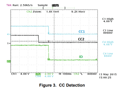
    Once a connection is made, the TUSB319-Q1 presents as a DFP to the DRP phone, which should begin negotiation between the two devices, with the phone resolving to configure as a UFP device. Once the connection is made, one CC pin should be pulled down, as it is not being used for the connection, while the other should resolve to a voltage depending on the settings of the TUSB319-Q1:

    This diagram in the datasheet shows what a connection would look like with the TUSB319-Q1 already enabled, waiting for a connection to a UFP device. Typically, the ID pin should go high for at least a moment once powered, and should go low after the CC negotiation process takes place. Currently, it looks like the ID pin doesn't even go high, or that both the CC pins settle at a lower voltage, which indicates to me that there is an issue with the the resistances that should be present on the UFP side of the connection.

    If you have contacts within USB IF that could help us get a response quickly that would be highly appreciated.

    I don't have any direct contacts to the USB-IF, just a general email they provide on their website: https://www.usb.org/compliancetools

    I already sent them an email for confirmation, but if you want, you can also send them an email.

    Thanks,

    Ryan

  • Hi Ryan, thank you for feedback. We do understand what you described above which is the normal DFP and UFP connection process. We also understand the DRP process. We really need to understand the TI device behavior in the following scenarios:

    1. If the phone does not support DRP and comes up as DFP what is the expected behavior?

    2. The TUSB319 does not support VCON so what is the device behavior when an active cable is connected? As you know when an active cable is connected the CC1 and CC2 are at logic <.85V on one line and between 0.85V-2.45V on the other and vice versa. So, what is the expected behavior of the TI device? 

  • Hi Fida,

    1. If the phone does not support DRP and comes up as DFP what is the expected behavior?

    Then both device will be set as a DFP, and there should be no connection between the two devices. The TUSB319-Q1 is hard-set as a DFP and cannot connect to any other DFP devices, so we would expect the ID pin to stay high. That's why it's odd that the ID pin is staying low, even though there should be no connection. One question I have is what the status of VBUS is over the cable while the silver box is disabled:

    Given that it looks like the Pixel10 is presenting as a DFP before the silver box is even enabled, I would like to see if it's supplying VBUS to the silver box because it believes there's a DFP connection. If VBUS is being supplied by the Pixel10, that may be affecting the performance of the TUSB319-Q1. Would it be possible to monitor VBUS before and after the silver box is powered?

    2. The TUSB319 does not support VCON so what is the device behavior when an active cable is connected? As you know when an active cable is connected the CC1 and CC2 are at logic <.85V on one line and between 0.85V-2.45V on the other and vice versa. So, what is the expected behavior of the TI device? 

    Because the TUSB319-Q1 does not support VCONN, when there is a connection we would expect there to be activity on one of the CC pins where the connection between the CC pins of the TUSB319-Q1 and the Pixel10 is taking place, while the other CC pin should be pulled down to GND and set at if not close to 0V. We see this for the most part in the waveforms provided, so I don't believe there is an issue there.

    I don't believe I've seen a schematic yet for this part, would it be possible to send that over? Or at the very least, what is the current setting for the CURRENT_MODE pin?

    For the EMarker cables being used, what is the current rated for these cables? Do they require 3A of current, or 5A of current minimum? Our TUSB319-Q1 can only provide a max of 3A of current.

    Also, I did receive a response from a USB-IF admin. They confirmed that for Type-C/PD interoperability testing, e-Marker type-C cabling testing is required for inter-op testing. Just to confirm, are you using PD functionality and/or USB3 data lanes, or is this port being used for strictly USB2?

    Thanks,

    Ryan

  • We can capture more waveforms of the Vbus when Silverbox off and when it turns on. I just wanted to add that this failure only happens when the Silverbox and Phone are already connected via the E-Marker USB cable and we reboot the Silverbox. However If you unplug the USB connector and plug it back in then everything works fine thereafter. 

    I will provide snip it of the schematic for this part via email. The current mode is set to 3A via10K to VCC

    I will double check the E-Marker cable current rating

    We are not using the PD functionality and yes one port is 2.0 USB data and charging and the second port is charging only no data. .  

  • Hi Fida,

    I will provide snip it of the schematic for this part via email. The current mode is set to 3A via10K to VCC

    I would like to confirm, the ID pin is being pulled-up to VCC with a 200KOhm resistor, correct? I don't see it on this schematic so I want to double check.

    We are not using the PD functionality and yes one port is 2.0 USB data and charging and the second port is charging only no data.

    Okay, good to know. I've asked the USB-IF whether Type-C/PD Functionality inter-op compliance testing is still needed in this case, and will let you know what I hear back.

    I will double check the E-Marker cable current rating

    Sounds good, please let me know.

    We can capture more waveforms of the Vbus when Silverbox off and when it turns on. I just wanted to add that this failure only happens when the Silverbox and Phone are already connected via the E-Marker USB cable and we reboot the Silverbox. However If you unplug the USB connector and plug it back in then everything works fine thereafter. 

    Got it, I wasn't totally sure what scenario the fail was happening so I appreciate the clarification. Given it only happens during reboot or power-up, my suspicion is that a CC controller on either side of the connection believes there is a connection while the Silverbox is rebooted due to the EMarker even though there should be no connection during reboot, and the CC controller does not break this connection until after the Type-C cable is unplugged and re-plugged.

    Thanks,

    Ryan

  • Hi Yvonne,


    For the Silverbox waveforms, can we get a waveform where it starts in the working scenario, I.E VBUS is being sent through to the Pixel10 so it’s charging, and then the silverbox is powered off for a moment then turned back on to put it in that failed charging state?


    What about a waveform monitoring the CC lines while the TUSB319-Q1/Hub is powered down to show that the CC lines are not high, and a waveform monitoring just the Pixel10 CC pins, not connected to the hub if possible, showing the state of the Pixel10 CC pins when using an EMarker VS not using an EMarker.


    Is there a specific process that can be done to replicate the ANKER failure, or is it pure chance? Is it common enough to reproduce or pure chance?


    Thanks,

    Ryan

  • Hi Ryan,

    This is interesting because you can see the Pixel 10 going to DRP on CC2 line when Vbus is off and then it thinks it detected a device (Rd) and pulls high. Yvonne will try to capture the voltage right before the CC2 pulls high. Just curios when the chip has no power is there a pull up/ down internally?  

    Thank You,

    Fida

  • Hi Fida,

    I see what you mean, I think I might have also noticed that on slide 6 of the presentation Yvonne sent over.

    I’ve asked internally to confirm whether there are any PU/PD when the TUSB319-Q1 has no power, and will let you know.

    Also, just to check since I didn’t see it in the schematic sent, is there any VBUS Discharge circuit for the VBUS_DET pin?

    Thanks,

    Ryan

  • Hi Ryan,

    Form me I don’t understand why the pixel 10 is pulling high. Please review the provided data and let me know your thoughts and if ready to provide technical explanation that we can add in the waiver request to USB IF. Thank you

    Thank You,

    Fida

  • Hi Yvonne and Fida,

    I’m also still trying to understand this. I’m still looking in the background for more details about the internal on the CC pins of the TUSB319-Q1 to see if there is some PU/PD while disabled. Does disconnecting and reconnecting the EMarker while the silver box is disabled have any effect? I don’t expect it to, but I just want to confirm. What about resetting the Pixel10?

    Would it be possible to test this with the TUSB319EVM or TUSB320EVM set to DFP and see if this same performance occurs, or if there is a difference in performance? I want to confirm whether or not it is a design issue.

    I was also thinking about disconnecting the VBUS Discharge circuit and ensuring that isn’t an issue either. I would also like to remove the caps on the DIR/CURRENT_MODE pins to ensure those aren’t an issue, since we don’t typically recommend those.

    I’m looking into this still, I will feed back once I have more info as well.

    Thanks,

    Ryan

  • Hi Ryan,

    Do you have a TUSB319EVM or TUSB320EVM board that we can get to try?

    Yvonne, can we try the test conditions below:

    • Disconnecting and reconnecting the EMarker while the silver box is disabled
    • Remove the caps on the DIR/CURRENT_MODE pins
    • Disconnecting the VBUS Discharge circuit

    Thank You,

    Fida

  • Hi Fida,

    Good to hear, I was just about to reach out on that.

    One thing I want to note with the DRP CC toggling, I’ve looked over this a bit. Typically, for a DRP connection, both CC lanes should be toggling high and low, alternating between the two. However, in all the waveforms we’ve seen so far, it looks like there is only ever activity on one of the CC pins when connected:

    Typically, this toggling should happen on both pins. Would it be possible to just connect an iPhone to the breakout through a regular type-C cable without being connected to the silver box, to ensure that CC toggling is on seen on both sides?

    Thanks,

    Ryan