


Part Number: DP83867E
Our design is utilizing two of these PHYs. One is acting as an SGMII to 1000Base-T transceiver and the other is a RGMII to 1000Base-T transceiver.
In the schematic currently, we have 0 ohm resistors drawn as Do Not Installs on all the pins that are used for Tx and Rx skew control via bootstrapping.
Referring to this note in the Data Sheet:
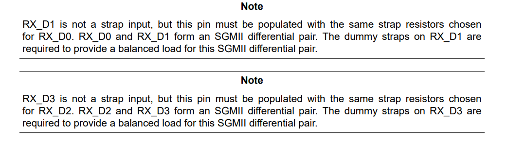
Does this mean we should add hooks in the design via 0 ohm resistors on the RX_D3 and RX_D1 pins as well? Does this not apply to RGMII and only to SGMII?
Also, given this note from the Data Sheet:
"Strap modes 1 and 2 are not applicable for RX_CTRL. The RX_CTRL strap must be configured for strap mode 3 or strap mode 4. If the RX_CTRL pin cannot be strapped to mode 3 or mode 4, bit[7] of Configuration Register 4 (address 0x0031) must be cleared to 0. Autoneg Disable can always be set to 0 when using gigabit Ethernet."
Does this mean that we can not have these 0 ohm resistors as Do Not Install placeholders on the RX_CTRL pin?
Finally, for the SGMII circuit, we have strap resistors on RX_DR/SGMII_SOP which is being utilized as an output. Should we not use strap resistors on any outputs that are in use?
