This thread has been locked.

If you have a related question, please click the "Ask a related question" button in the top right corner. The newly created question will be automatically linked to this question.

TUSB1104: How to enable Adaptive Equalization in TUSB1104 for USB3.2 2x2 successful Communication

Part Number: TUSB1104

Dear Sir/Madam,

We have developed High Speed FMC Daughter Card for USB3.2 2x2 Communication using TUSB1104.

We need to enable Adaptive Equivalization and require step by step by instruction to enable access Register and map the values. 

Although we have gone through Datasheet in details but require valuabel support to save time and efforts in this regards.

With reference to Table 7-9 of Device Registers which one are playing role for Full Adpative Equalization? Let us know if any TI User guide available which can explain Register Settings in detail. 

We have already enabled I²C mode and AEQ is typically enabled by default, but confirming it if any register configuration is recommended. 

  • Hi,

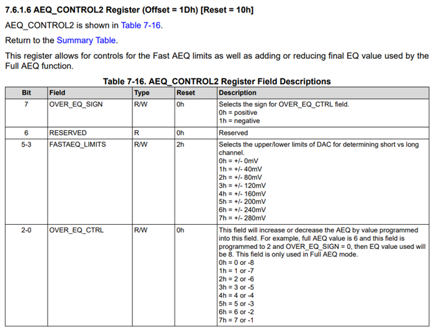
    They key registers to enable AEQ are as follows:

    I recommend switching to full AEQ algorithm II this is a more efficient algorithm. 

  • Dear Vishesh, 

    Thank you so much for your creative support even over weekend. I really appreciate your work and support dedication. 

    Apart from AEQ_Control_1 and AEQ_Control_2 registers, are there any other registers need to take care for configuration under the Adaptive Equalization Run?

    Also, regarding General_1 register, Bit-4 about EQ_OVERRIDE, we are planning to set it 1h, but from where it will take EQ settings which are based on programmed value of each of the EQ registers? I mean to say which EQ Registers setting will be considered. Where those EQ Registers present?

    Under AEQ mode, does TX1EQ_CTRL and TX2EQ_CTRL registers need to do configuration for De-Emphasis and Pre-Shoot features? Or it will be automatically taken care during Adaptive Equalization mode?

    Kindly guide me.

  • Hi Himanshu,

    Our team is out today on US holiday. Please expect a response on 1/20 after the holiday.

    Thanks,

    Ryan

  • Dear Ryan, 

    Thanks for your response.

    Dear Vishesh, 

    In addition, with my yesterday queries, I have below queries.

    Regarding Genera_1 Register (0A), how "Flip_Sel" bit can be controlled? Can it be automatically controlled by TUSB1104?

    Suppose I need to write this register value during validation phase through Command Prompt, I mean to say what should be General_1 register value I need to write, 0x91 or 0x95

    Today I have studied and tried attached registers setting which are very closely matched with our configuration requirements.

    I have tried these setting but observed failure (LFPS Time OUT). I have changed few values but still failure persist. I am wondering from where I need to start the registers bits change and which register bits.

    Actually, I have not high bandwidth oscilloscope so I cannot measure signal quality. I will get chance to do testing (16-Hours) probably in next week might be at GRL LAB.

    But slot time is very limited. So, I am bit afraid that where and which register bits will give quick results. Can you please guide me about step-by-step instruction? Test Slot is very costly so very high pressure to get success in this time frame.

    I am planning to do well preparation with your valuable help in advance to save time and achieve milestone of success or closer to success at least. 

  • Hi,

    Apart from AEQ_Control_1 and AEQ_Control_2 registers, are there any other registers need to take care for configuration under the Adaptive Equalization Run?

    These registers will enable and tune the adaptive EQ for function. Finer tuning can be done but is not typically required.

    Also, regarding General_1 register, Bit-4 about EQ_OVERRIDE, we are planning to set it 1h, but from where it will take EQ settings which are based on programmed value of each of the EQ registers? I mean to say which EQ Registers setting will be considered. Where those EQ Registers present?

    The TSUB1104 samples the status of the GPIO pins on startup. This is the default configuration of the TUSB1104. If EQ override is not set, then the samples values of the EQ pins such as SSEQ1 will be the EQ and cannot be changed. 

    Under AEQ mode, does TX1EQ_CTRL and TX2EQ_CTRL registers need to do configuration for De-Emphasis and Pre-Shoot features? Or it will be automatically taken care during Adaptive Equalization mode?

    These registers will control the SSTX and SSRX pins. These will be internally facing, so these will not need to be adjusted for TX eye diagram testing. You may need to adjust this for RX JTOL testing if the trace length on the PCB is very long. 

    Regarding Genera_1 Register (0A), how "Flip_Sel" bit can be controlled? Can it be automatically controlled by TUSB1104?

    This is controlled by an external PD/CC controller, by the SoC or by PUP and PDOWN resistors. I recommend using a GPIO pin of the CC and PD controller to control this pin

    I have tried these setting but observed failure (LFPS Time OUT). I have changed few values but still failure persist. I am wondering from where I need to start the registers bits change and which register bits.

    The LFPS signaling is triggered after RX detect has taken place. are 50ohhm terminations present on the downstream USB Type-C pins?

  • Dear Vishesh,

    Thank you so much for your support.

    Regarding your feedback about Flip_Sel bit, "This is controlled by an external PD/CC controller, by the SoC or by PUP and PDOWN resistors. I recommend using a GPIO pin of the CC and PD controller to control this pin"

            - Does it mean I don't need to write any value in Genera_1 Register (0A), neither 0x91H nor 0x95H ? Please guide.

    Regarding your below question,

    The LFPS signaling is triggered after RX detect has taken place. are 50ohhm terminations present on the downstream USB Type-C pins?


          - In USB Device IP core, we only enable RX termination so that Host can detect RX termination change and can switch to next state. Currently device has no capability that it can detect RX termination change of HOST. Hence our USB IP core will enable only RX termination register in RX detect state and then switch to next state.

    Kindly provide your valuable feedback. 

  • Hi,

    Regarding your feedback about Flip_Sel bit, "This is controlled by an external PD/CC controller, by the SoC or by PUP and PDOWN resistors. I recommend using a GPIO pin of the CC and PD controller to control this pin"

            - Does it mean I don't need to write any value in Genera_1 Register (0A), neither 0x91H nor 0x95H ? Please guide.

    The normal and flipped orientation are detected by a CC or PC controller as per the USB Type-C spec. Once the cable orientation is detected that information should be sent to the TUSB1104. This can be done via I2C or GPIO. Typically a PD controller (I2C host) will be designed to automatically write the orientation of the connection to the TUSB1104 (I2C device)

    The LFPS signaling is triggered after RX detect has taken place. are 50ohhm terminations present on the downstream USB Type-C pins?


          - In USB Device IP core, we only enable RX termination so that Host can detect RX termination change and can switch to next state. Currently device has no capability that it can detect RX termination change of HOST. Hence our USB IP core will enable only RX termination register in RX detect state and then switch to next state.

    The RX detection should look as follows for proper operation:

    1) power on the TUSB1104 & power on USB host

    2) USB host sends RX detect waveforms across the SSTX line. The TUSB1104 reciever these RX detect wave forms.

    3) TUSB1104 send RX detect waveforms on CTX1 and CTX2.

    4) A device is seen on the USB lines, so terminations are present.

    5) TUSB1104 sees terminations on the CTX1 or CTX2 pins and enables terminations on SSTX side.

    6) Host sees termination of the TUSB1104 and progresses to LFPS and the the next state.