This thread has been locked.

If you have a related question, please click the "Ask a related question" button in the top right corner. The newly created question will be automatically linked to this question.

THVD1420: R pin pull-down

Part Number: THVD1420

Hi All,


I have a question about the THVD1420.
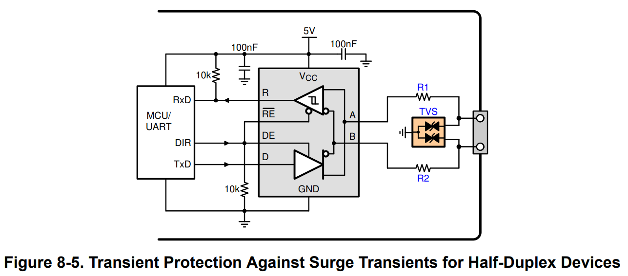
I was unable to communicate via RS485 properly using the circuit diagram in the datasheet below.

image.png


When I changed the pull-up on the R pin to a pull-down, communication was successful.

Why does pulling down the R pin allow communication to proceed normally?


Best Regards,
Ishiwata

  • The pull-up on the R pin has an effect only when the receiver is disabled (/RE high) or powered off.

    In general, the protocols used with RS-485 have a high logic level when idle. I do not know what protocol you're using.

  • Hi Ishiwata,

    If you believe the transceiver is not working properly, please provide a waveform of the /RE, R, and A/B pins while the issue is occurring. As Clemens mentioned, the pullup/down resistor is applicable when the receiver is off (unless the resistor is incorrectly specced).

    Best,

    Ethan

  • Hi Clemens and Ethan,

    Thank you for your reply.

    I apologize for not understanding.

    I understand that the R terminal does not necessarily require a pull-up or pull-down. Is this correct?

    The R terminal is connected to the MCU.
    I think the reason it doesn't work properly if it's pulled up is because the MCU cannot detect a low start bit. Is this correct?

    Best Regards,
    Ishiwata

  • Hi Ishiwata,

    I understand that the R terminal does not necessarily require a pull-up or pull-down. Is this correct?

    This is correct. The biasing resistor is there to help with idle conditions which can negatively affect certain protocols. 

    I think the reason it doesn't work properly if it's pulled up is because the MCU cannot detect a low start bit. Is this correct?

    The transceiver will be able to drive the R line low even with a pullup resistor (assuming you selected the correct resistor value). Either way if this resistor is causing issues, you can remove it. 

    Best,

    Ethan

  • Hi Ethan,


    Thank you for your support.

    The pull-up resistor is 10kΩ.
    I will send the customer's circuit diagram to you via private message.
    Please let me know if there is anything you are concerned about.
    In the customer's circuit diagram, the pull-up resistor is not on the THVD1420 side, but on the MUC at the end of the connector.

    Also, I am currently checking the waveforms, and will send them to you once they are available.


    Best Regards,
    Ishiwata

  • Hi Ishiwata,

    I don't see a pulldown resistor on the DE pin, but I would recommend this in case its not there. This ensures the transceiver isn't accidentally transmitting while powering on/off. Overall, no concerns with that schematic you sent me.

    When you get the waveforms, try to probe as close to IC pins as possible.

    Best,

    Ethan

  • Hi Ethan,

    I apologize for the late response.

    The customer reported that communication was successful when they applied an oscilloscope probe.

    The likely reason for this is that the impedance of the connected MUC was high, so when the oscilloscope probe was applied,
    the impedance decreased, stabilizing the signal.

    As for the fact that it worked properly with pull-down, this is probably because the start bit was low,
    which maintained a low level compared to when it was pulled up,
    which is why it worked properly.

    Best Regards,
    Ishiwata