This thread has been locked.

If you have a related question, please click the "Ask a related question" button in the top right corner. The newly created question will be automatically linked to this question.

TUSB1142: About the resistor and AC cap in TUSB1142

Part Number: TUSB1142
Other Parts Discussed in Thread: STRIKE,

Hi AE,

   Regarding the RX path from the Type-C connector to the TUSB1142IRNQR, based on reference designs and project applications:  

a. Is it acceptable to include AC coupling capacitors (330 nF), a 220 k discharge pull-down resistor, a common-mode choke (with 0-ohm option), and ESD protection on the RX path? 

b. What is the recommended order of these four components from the Type-C connector to the TUSB1142IRNQR? 

c. Under what conditions is this implementation required, and are there any reference schematics or design guidelines available?
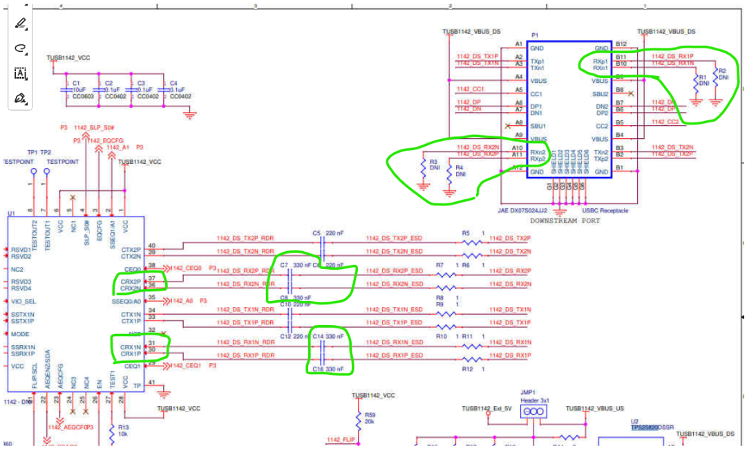
image.png


Best Regards

  • Hi,

    a. Is it acceptable to include AC coupling capacitors (330 nF), a 220 k discharge pull-down resistor, a common-mode choke (with 0-ohm option), and ESD protection on the RX path? 

    Yes this is acceptable. Typically CMCs add some series resistance to the signal path and are not recommended. However, if they are required to too tight EMI requirements, then a resistor:CMC co-lay is a good option. 

    b. What is the recommended order of these four components from the Type-C connector to the TUSB1142IRNQR? 

    There are two primary solutions:

    1) protection from ESD: USB Type-C connector -> ESD -> CMC -> Cap -> TUSB1142. In this configuration a VBUS sort will likely damage the ESD diodes.

    2) protection from VBUS short: USB Type-C connector -> Cap -> ESD -> CMC -> TUSB1142. In this configuration a ESD strike will break the caps.

    I recommend solution 1.

    c. Under what conditions is this implementation required, and are there any reference schematics or design guidelines available?

    The 330nF cap is an optional component. This is used to ensure AC coupling on the SSRX. This allows for improved interoperability. I recommend having this cap present.

    The 220K PDOWN is also an option component. When USB data is being transmitted the 330nF will gather some charge. This 220K resistor ensures the cap is discharged during a hot plug event.

    The CMC is for EMI protection. Only use thsi if absolutely necessary.

    The ESD is to protect the internal devices against ESD events. This component is highly recommended.

    Our TUSB1142EVM is a good design to use for reference.

  • Hi AE,

           Regarding the 220 kΩ pull-down resistor, is there a recommendation to place it closer to the IC side or closer to the connector side?

           Additionally, could you advise whether the AC capacitors should be placed on the IC side or near the connector?   

    Best Regards

  • Hi Bruce,

     Regarding the 220 kΩ pull-down resistor, is there a recommendation to place it closer to the IC side or closer to the connector side?

    close to connector

           Additionally, could you advise whether the AC capacitors should be placed on the IC side or near the connector?   

    close to connector

    Typically the sigbnal path is as follows:

    Redriver (TUSB1142) -> ac cap (100nF/ 220nF cap for TX and 330nF cap for RX) -> 220K PDOWN resistor (may not need for TX) -> to ESD -> USB connector.