This thread has been locked.

If you have a related question, please click the "Ask a related question" button in the top right corner. The newly created question will be automatically linked to this question.

DS90UB947-Q1: Could you pls help review the Register setting value for DS90UB947?

Part Number: DS90UB947-Q1
Other Parts Discussed in Thread: ALP, USB2ANY

Dears,

    Occasionally, the output from DS90UB947TRGCRQ1 to the display screen may exhibit image jittering.The customer suspects that the issue is caused by a problem with the DS90UB947 register settings. Could you pls help review the Register setting value for DS90UB947?

    Can DS90UB947TRGCRQ1 output color bars by itself? If so, which command should be used?

DS90UB947 Register value_1.txt  

  • Hi Jon,

    On the deserializer, are there any LOCK drops detected? You can check by probing the LOCK pin on the DES.

    There are also CRC errors detected on the 0xA register of the serializer. Are these cleared at the start and still observed after flickering?

    How frequently is the flickering observed and is it seen on multiple tested boards?

        Can DS90UB947TRGCRQ1 output color bars by itself? If so, which command should be used?

    To output color bars generated by the 947, you can use the pattern generation on the 947. The easiest way to do this would be connect to the device via I2C from your computer and use the FPD-Link GUI Analog LaunchPad. It has a tab for pattern generation to enter the timings, clock rates, and enable color bars and test pattern.

    Please let me know if you need clarification for this.

    Best regards,
    Ikram

  • Ikram,

         Thank you for your prompt response !

    1.The Lock pin remains at a high level.

    2.The value of register address 0x0a is not fixed. When displaying normally, the value of 0x0a varies at different times, and the same applies when displaying abnormally

    3.The frequency of abnormal display is relatively low, with an abnormality occurring once every dozens of power-on and power-off cycles

  • Hi Jon,

    1. Could you also describe what the issue observed is. Does it continuously flicker or is it occasional? Could you share an image or video of what this looks like

    If the issue occurs persistently, then it could also be related to Power-up cycle. Please check whether the sequence in datasheet "Power-Up Requirements and PDB Pin" section is followed.

    2. Does the value in register 0xA-0xB increase at various times? Could you monitor these registers over time and check.

    3. Please check with pattern generation whether the issue still occurs. 

    If the issue occurs with SER PatGen, then please try with DES PatGen. The deserializer can also be connected via I2C to the ALP program and programmed for pattern generation.

    What is the deserializer used here?


    Best regards,
    Ikram

  • hello,Haque

    1. Could you also describe what the issue observed is. Does it continuously flicker or is it occasional? Could you share an image or video of what this looks like
    If the issue occurs persistently, then it could also be related to Power-up cycle. Please check whether the sequence in datasheet "Power-Up Requirements and PDB Pin" section is followed.

    reply:This is an occasional issue with a probability of approximately 1/100. For details, refer to the attached video.

    The power-up sequence complies with the "Power-Up Requirements and PDB Pin" section in the datasheet.

    2. Does the value in register 0xA-0xB increase at various times? Could you monitor these registers over time and check.

    reply:The values in registers 0xA-0xB only change (without showing a continuous increasing trend).

    3. Please check with pattern generation whether the issue still occurs. 

    If the issue occurs with SER PatGen, then please try with DES PatGen. The deserializer can also be connected via I2C to the ALP program and programmed for pattern generation.

    reply:Could you provide the configuration parameters for the SER PatGen test mode and DES SER PatGen test mode? The current resolution is 1024×600. we do not have the ALP program.

    What is the deserializer used here?

    reply:DS90UB948

  • Hi Weng,

    Please download the ALP program from this link: https://www.ti.com/tool/ALP

    Then you could run it from your laptop with the I2C connected with USB2ANY or an Aardvark.

    For the manual register parameters, we would need information for the display blankings (front porch, back porch, sync width) and pixel clock rate along with the active period (1024 x 600).  


    Best regards,
    Ikram

  • Hi haque

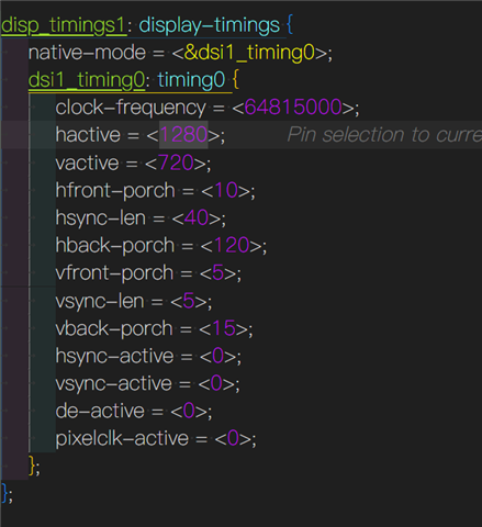
    display blankings see figure.

     display

    add video 

  • Hi Weng,

    Please try with this script below for test pattern:

    ## Total Horizontal Pixels = 1450 = 0x5AA
    ## Total Vertical Lines = 745 = 0x2E9
    ## Active Horizontal Pixels = 1280 = 0x500 
    ## Active Vertical Lines = 720 = 0x2D0
    ## Horizontal Back Porch = 120 = 0x78
    ## Vertical Back Porch = 15 = 0x0F
    ## Horizontal Sync = 40 = 0x28
    ## Vertical Sync = 5 = 0x05
    ## Horizontal Front Porch = 10 = 0x0A  
    ## Vertical Front Porch = 5 = 0x05
    ## Horizontal Sync Polarity = Positive
    ## Vertical Sync Polarity = Positive
    ## Bits per pixel = 24 = 0x18
    ## Pixel Clock = 64.86 MHz 
    
    ## Pixel clock speed is set by M/N divider and set to be close to the required timings
    
    serAddr = 0x18
    
    board.WriteI2C(serAddr,0x66,0x03) # N = 37 (0x25)
    board.WriteI2C(serAddr,0x67,0x25)
    
    board.WriteI2C(serAddr,0x65,0x1A) # M = 3 (0x03)
    board.WriteI2C(serAddr,0x67,0x03)
    
    board.WriteI2C(serAddr,0x66,0x07) # 8 LSB active horizontal (1280 = 0x500)
    board.WriteI2C(serAddr,0x67,0x00)
    
    board.WriteI2C(serAddr,0x66,0x08) # 4 LSB active vertical and 4 MSB active horizontal
    board.WriteI2C(serAddr,0x67,0x05)
    
    board.WriteI2C(serAddr,0x66,0x09) # 8 MSB active vertical (720 = 0x2D0)
    board.WriteI2C(serAddr,0x67,0x2D)
    
    board.WriteI2C(serAddr,0x66,0x04) # 8 LSB total horizontal (1450 = 0x5AA)
    board.WriteI2C(serAddr,0x67,0xAA)
    
    board.WriteI2C(serAddr,0x66,0x05) # 4 LSB total vertical and 4 MSB total horizontal
    board.WriteI2C(serAddr,0x67,0x95)
    
    board.WriteI2C(serAddr,0x66,0x06) # 8 MSB total vertical (745 = 0x2E9)
    board.WriteI2C(serAddr,0x67,0x2E)
    
    board.WriteI2C(serAddr,0x66,0x0C) # horizontal back porch (120 = 0x78)
    board.WriteI2C(serAddr,0x67,0x78)
    
    board.WriteI2C(serAddr,0x66,0x0D) # vertical back porch (15 = 0x0F)
    board.WriteI2C(serAddr,0x67,0x0F)
    
    board.WriteI2C(serAddr,0x66,0x0A) # horizontal sync width (40 = 0x28)
    board.WriteI2C(serAddr,0x67,0x28)
    
    board.WriteI2C(serAddr,0x66,0x0B) # vertical sync width (5 = 0x05)
    board.WriteI2C(serAddr,0x67,0x05)
    
    board.WriteI2C(serAddr,0x66,0x0E) # horizontal and vertical sync polarity
    board.WriteI2C(serAddr,0x67,0x00)  # Both positive polarity
    
    board.WriteI2C(Des_addr,0x65,0x04) # internal timing, internal clock
    board.WriteI2C(Des_addr,0x64,0x05) # enable patgen
    
    # end of script


    Also, please check whether the errata provided by TI are implemented during power-up. If you haven't already added them, please ask your field applications contact about the errata document.

    Please let me us know whether the test pattern shows the issue. You could power-cycle and then program test pattern, to check whether the flickering occurs after many cycles.

    Best regards,
    Ikram