This thread has been locked.

If you have a related question, please click the "Ask a related question" button in the top right corner. The newly created question will be automatically linked to this question.

TUSB321AI: TUSB321AI || DFP mode not working

Part Number: TUSB321AI
Other Parts Discussed in Thread: TUSB321, HD3SS3212, HD3SS3220

Dear TI Support,

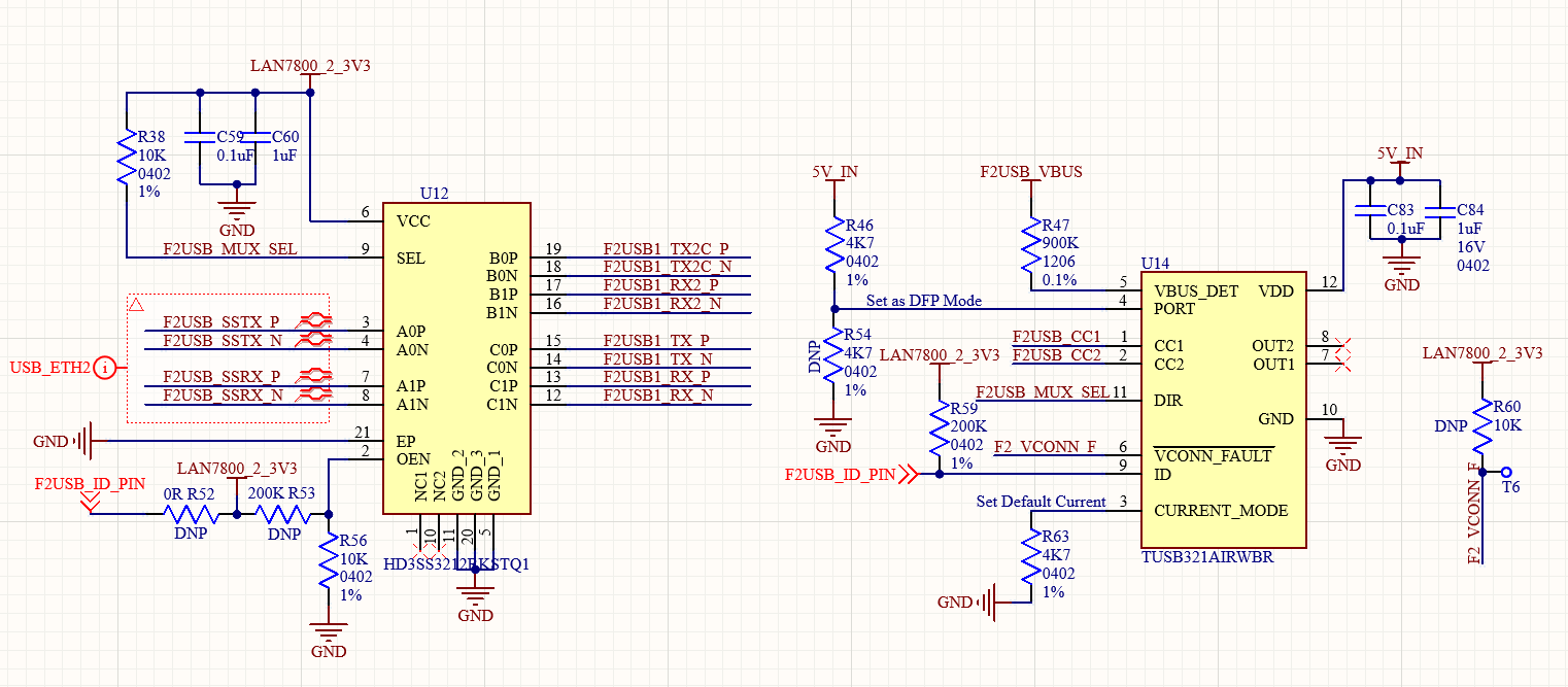
We have developed a custom board, and for the charging section we are using the TUSB321AIRWBR part.

The part number is TUSB321AIRWBR. Our application uses a custom board connected to a mobile phone, where we require simultaneous charging and data communication between the mobile device and the custom board.

We have configured the IC in DFP mode, but the issue still persists. for your reference schametic section attached.

Issue:- When I connect the phone to the custom board, the phone is not detected, and even though the load switch is enabled for mobile charging, the phone does not charge. 

Please suggest where the issue might be.

image.png


Thanks and regards,

Jai Kishan

  • Hi,

    Can you share waveforms of CC1, CC2, ID, and VBUS from one capture? I would like to see the order of events.

  • Hello Vishesh,

    I have captured and attached the wave form of CC1, CC2, ID PIN and VBUS.

    Ch 1. Yellow line:- Vbus

    Ch 2. Sky blue Line:- ID PIN

    Ch 3. Magent Line :- CC1

    Ch 4. Blue Line:- CC2

    Below attchement 1:- when phone is not connected to custom board.

    Below attchement 1:- when phone is connected to custom board.

    Below attchement 2:- We have capture below event when phone dettached from custom board. 

    Below attchement 3:- We have capture below event when phone attached from custom board. 

    Vbus is not getting high.

    Thanks and regards,

    Jai Kishan

    +91 7737779900

  • Hi,

    Thanks for the waveforms.

    Ch 1. Yellow line:- Vbus

    Ch 2. Sky blue Line:- ID PIN

    Ch 3. Magent Line :- CC1

    Ch 4. Blue Line:- CC2

    Below attchement 1:- when phone is not connected to custom board.

    CC1 and CC2 is held high when nothing is connected (this is correct)

    ID pin is high meaning nothing is connected (this is correct)

    Vbus is low (this is correct)

    Below attchement 1:- when phone is connected to custom board.

    Once connection has taken place both CC1 and CC2 go low. The slight DC voltage seen on CC2 shows the phone is connected in the flip orientation. (this is correct)

    ID pin is pulled low (this is correct)

    Vbus remains low (this is incorrect). When the ID pin is pulled low, this should be a trigger for the Vbus switch. How is the Vbus switch being controlled in your implementation?

    Below attchement 2:- We have capture below event when phone dettached from custom board. 

    CC1 and CC2 both revert to high once disconnection has taken place (this is correct)

    ID pin goes back to high after disconnect (this is correct)

    Vbus should go from high to low (this is incorrect)

    Below attchement 3:- We have capture below event when phone attached from custom board. 

    CC1 goes from high to low, but CC2 remains low. This is not expected behavior. Both CC1 and CC2 should go from high to low.

    ID pin goes from high to low. (this is correct)

    Vbus stays low. (This is not corrrect)

    Vbus is not getting high.

    Based off of the waveforms shared I see that the ID pin is toggling correctly. This means that part is correctly detecting that a connection takes place. Can you confirm how ID pin routed in your system? This pin should be a trigger that enables Vbus, but it seems Vbus is not being enabled. The trigger is operating correctly, but the switch is not. 

  • Hi Vishesh,

    Thank you for the clarification.

    In our custom board, the load switch was not getting enabled, which is why VBUS was not going high. We have now updated the controller firmware, and VBUS is getting enabled when the phone is plugged into the custom board.

    Now we have two quetions:

    1. When we connect the phone to the custom board, the phone displays the message “Check your charger connection.”

    2. The phone data connection is not established between the phone and the custom PCB. 

    Could you clarify these points.

    Thnaks and regards,

    Jai Kishan

  • Hi,

    1. When we connect the phone to the custom board, the phone displays the message “Check your charger connection.”

    I'm not sure exactly what you cause this. Can you try replacing the cable as shown? If not it could be due to the power advertisement. Currently the PCB is advertising 5V 500mA on Vbus. This may be much slower charging speed than what the phone is expecting, this could possibly cause this image to trigger.

    2. The phone data connection is not established between the phone and the custom PCB. 

    Do you mean no connection at all? Both USB2 and USB3 connections are not enumerating?

    If nothing is enumerating please probe the inputs and outputs of the MUX to see if signals are propagating correctly.

  • Hi Vishesh,

    1. We changed the cable, but the same issue is still occurring. We had set the default current earlier; now we will set the current to 1.5 A and share the results.

    2. The USB 3.0 connection enumerates when the supply to the TUSB321AI IC is disconnected. However, when power is applied to the TUSB321AI, the USB ports do not enumerate and the device only shows charging with the message “Check your charger connection.” Charging and USB port enumeration are not working simultaneously.

    3 I would like to confirm whether this IC supports simultaneous data transfer and charging.
    If it does, please help us understand why this issue is occurring in our setup.
    If it does not support this functionality, please suggest an alternative IC that would be suitable for our application.

    Our application:- Our application requirement is that USB port should enumerate, and we should be able to enable or disable phone charging using a load switch whenever required and we don't need fast charing support we need simple(900mA 5V at USB3.0)

    I hope this clearly explains our requirement and what exactly we are trying to achieve.

    Thanks and regards,

    Jai Kishan

  • Hi,

    2. The USB 3.0 connection enumerates when the supply to the TUSB321AI IC is disconnected. However, when power is applied to the TUSB321AI, the USB ports do not enumerate and the device only shows charging with the message “Check your charger connection.” Charging and USB port enumeration are not working simultaneously.

    Can you share a full schematic of your system?

    The CC lines are not terminated, so enumeration should not happen. Most likely the flip logic is incorrect in this case.

    Please use the following test procedure:

    1) With the TUSB321 powered down can you test both orientation of the USB Type-C cable?

    2) Power the TUSB321 and probe the DIR pin. See the status of DIR in the normal and flipped orientations.

    3) Use a continuity tester to see if the MUX is being routed correctly. If SEL = 0, then the common signals should be connected to port A. If SEL =1, then the common signal should be routed to port B. 

    4) Make sure the DIR polarity of TUSB321 matches the desired routing of HD3SS3212

    3 I would like to confirm whether this IC supports simultaneous data transfer and charging.
    If it does, please help us understand why this issue is occurring in our setup.
    If it does not support this functionality, please suggest an alternative IC that would be suitable for our application.

    It may be easier to use the HD3SS3220 which incorporates the TUSB321 and HD3SS3212 into a single package.

  • Hello Vishesh,

    I am unable to upload the full schematic PDF so i am attaching the screenshot of the schematic.

    We have follow the below points;

    1) With the TUSB321 powered down can you test both orientation of the USB Type-C cable?

      We have tested the both orientation that is correct.

    2) Power the TUSB321 and probe the DIR pin. See the status of DIR in the normal and flipped orientations.

      DIR PIN is correctly HIGH and LOW when the cable is normal and flipped.

    3) Use a continuity tester to see if the MUX is being routed correctly. If SEL = 0, then the common signals should be connected to port A. If SEL =1, then the common signal should be routed to port B. 

     MUX  is properly working When the SEL=0 the Port-A to Port-B routed we have tested with mulitimeter, and SEL=1 then Port-A to Port-C routed correctly.

    4) Make sure the DIR polarity of TUSB321 matches the desired routing of HD3SS3212

      polarity is also match.

    It may be easier to use the HD3SS3220 which incorporates the TUSB321 and HD3SS3212 into a single package.

      Thnaks for your suggetion, In second revison we will definatly use the HD3SS3220 single IC, but now we need to run existing custom PCB board. If it is not run we will not proceed with HD3SS3220 IC

    The IC is not working as expected, Is this possible to visit technicial in our office to solve this issue?

    Our application block diagram:-

    Thanks and regards,

    Jai Kishan

  • Hi,

    It may be best to start with a remote debug. 

    Can you probe the CTX connections and see if the USB host/ device is outputting LFPS waveforms. This should look similar to a clock.

  • Hi,

    Please find the below LFPS waveforms:-

    Please suggest a suitable solution to help us bring up our board successfully.

    Thanks and regards,

    Jai Kishan

  • Hi,

    If LFPS waveforms are being sent out, then the MUX and TUSB321 are operating correctly. We see that data is being transmitted from the host to the connector. Is it possible there is an issue in the USB firmware on the host side?

  • Hi Vishesh,

    There is no firmware upload on the host side we connect the phone simply.

    As I mentioned earlier, when VCC is not applied to the TUSB321, the mobile port gets enumerated; otherwise, it does not. Therefore, we first removed the supply from the TUSB321 and then captured the waveform while applying VCC. In this case, the phone was not enumerated.

    Once again, I would like to summarize the issue below:

    1. When VCC is applied to the TUSB321, the mobile port does not get enumerated; only the phone charges.

    2. When VCC is not applied to the TUSB321, the phone does not charge, but the mobile port gets enumerated.

    Both charging and port enumeration are not working at the same time.

    Thanks and regards,

    Jai Kishan

  • Hi,

    • When VCC is applied to the TUSB321, the mobile port does not get enumerated; only the phone charges.

    • When VCC is not applied to the TUSB321, the phone does not charge, but the mobile port gets enumerated.

    The LFPS waveforms shared are when VCC is not supplied to TUSB321?

    Please test everything with power supplied to TUSB321. Can you share what the USB outputs look like when TUSB321 is powered. 

  • 2) Power the TUSB321 and probe the DIR pin. See the status of DIR in the normal and flipped orientations.

      DIR PIN is correctly HIGH and LOW when the cable is normal and flipped.

    3) Use a continuity tester to see if the MUX is being routed correctly. If SEL = 0, then the common signals should be connected to port A. If SEL =1, then the common signal should be routed to port B. 

     MUX  is properly working When the SEL=0 the Port-A to Port-B routed we have tested with mulitimeter, and SEL=1 then Port-A to Port-C routed correctly.

    4) Make sure the DIR polarity of TUSB321 matches the desired routing of HD3SS3212

      polarity is also match.

    If the lanes are all properly routed and a continuity test proves that the signals are routed appropriately. The MUX is being set correctly. This is why I asked for LFPS waveforms. 

  • Hi Vishesh,

    Please suggest us what should we do now?

    Thanks 

    Jai

  • Take LFPS waveforms with the TUSB321 enabled.

  • Hi Vishesh,

    I have already informed you that we have enabled the TUSB321 in DFP mode, but the port is not enumerating, which is why I am unable to capture the LFPS waveforms. This issue cannot be debugged remotely. If possible, arranging a visit by a technical engineer would help resolve the issue more effectively.

    Please review the schematic and let us know if there is any mistake in the configuration that could be causing the IC not to work. If all configurations are correct, it should work as expected, right?

    We request you to please provide a solution at the earliest, as our project is currently stuck due to this issue. If this IC is not suitable for our application, please let us know so that we can move forward and look for an alternative IC.

    Please reply my all points.

    Thanks and regards,

    Jai Kishan

  • Hi Jai,

    Unfortnately, we likely will not be able to arrange a physical meeting to debug this. If needed, we can setup a meeting online to discuss.

    One thing I would like to check, I noticed that you said when the TUSB321 is disabled, you can see a USB 3.0 connection. Do you mean that you can see the phone being charged and a connection, or just a USB3.0 connection with no charge?

    If possible, I would like to monitor the same lines as before (CC lines, ID, VBUS) while the TUSB321AI is disabled, to see what the difference is between the two. 

    When the TUSB321AI is disabled, it should enter a state called "dead-battery" mode. This will cause the TUSB321AI to configure as a UFP in the case where there is no power provided to the IC. If you are seeing a USB3 connection but not charging, that may explain it.

    Are you able to see a USB2.0 connection fine when the CC controller is enabled? Or can you not get any connection at all?

    Would it be possible to show where the ID pin is routed? I see the pin has a net name, but not where it goes.

    Thanks,

    Ryan

  • Unfortnately, we likely will not be able to arrange a physical meeting to debug this. If needed, we can setup a meeting online to discuss.

     :- An online meeting will also help with debugging. Please schedule it as soon as possible.

    One thing I would like to check, I noticed that you said when the TUSB321 is disabled, you can see a USB 3.0 connection. Do you mean that you can see the phone being charged and a connection, or just a USB3.0 connection with no charge?

     :- Right only show the USB3.0 connection with no charge.

    If possible, I would like to monitor the same lines as before (CC lines, ID, VBUS) while the TUSB321AI is disabled, to see what the difference is between the two. 

    When the TUSB321AI is disabled, it should enter a state called "dead-battery" mode. This will cause the TUSB321AI to configure as a UFP in the case where there is no power provided to the IC. If you are seeing a USB3 connection but not charging, that may explain it.

    Are you able to see a USB2.0 connection fine when the CC controller is enabled? Or can you not get any connection at all?

     :- When i enable the TUSB321, i am unable to see USB connection only show charging connection.

    Would it be possible to show where the ID pin is routed? I see the pin has a net name, but not where it goes.

     :-  ID pin is routed to MCU image given below


    Thanks 

    Jai Kishan

  • Hi Jai,

    :- An online meeting will also help with debugging. Please schedule it as soon as possible.

    Does 9AM Dallas time (UTC -6) Friday work? Do you have an FAE you can reach out to to help organize a meeting? If not, please send an email to Randy Lawson (r-lawson@ti.com) and attach a link to this E2E so he has reference as to what this is in relation to.

    One thing I would like to check, I noticed that you said when the TUSB321 is disabled, you can see a USB 3.0 connection. Do you mean that you can see the phone being charged and a connection, or just a USB3.0 connection with no charge?

     :- Right only show the USB3.0 connection with no charge.

    Is this in both directions of the type-C cable, or in only one direction? If there is no CC controller, typically the USB3.0 connection will only work in one direction, or will only work in USB2.0. If it works in both directions, that would lead me to think there may be an issue in the routing of the USB 3.0 signal or the routing at the mux. Please help to confirm if the USB3.0 signal works in both directions without the CC controller, or only one direction.

    No charge indicates that either the phone is configuring as a UFP, or that VBUS is not being applied, which makes sense.

    When i enable the TUSB321, i am unable to see USB connection only show charging connection.

    One thing I would like to test if that's okay, if you disable the HD3SS3212 by pulling the OEN pin high, are you able to see a USB3.0 or USB2.0 connection in either direction? I would like to see if the mux is having any effect or not on the connection.

    At the very least, regardless of whether there is a CC controller or not, if VBUS is being applied to the port, you should be able to see a USB2.0 connection. If you don't even see a USB2.0 connection, that would indicate to me that the error may be somewhere else in the system.

    Thanks,

    Ryan

  • Hello Ryan Kitto,

    Does 9AM Dallas time (UTC -6) Wednesday work possible if yes I will send an email to Randy Lawson (r-lawson@ti.com) and attach a link?

    Is this in both directions of the type-C cable, or in only one direction? If there is no CC controller, typically the USB3.0 connection will only work in one direction, or will only work in USB2.0. If it works in both directions, that would lead me to think there may be an issue in the routing of the USB 3.0 signal or the routing at the mux. Please help to confirm if the USB3.0 signal works in both directions without the CC controller, or only one direction.

    Jai Kishan Said:- When no power is applied on the TUSB321 then USB3.0 is works both direction. We have read the ID pin using MCU When the ID pin low the charging enables and load switch turns ON and power applies on Vbus. but phone does not charge.

    One thing I would like to test if that's okay, if you disable the HD3SS3212 by pulling the OEN pin high, are you able to see a USB3.0 or USB2.0 connection in either direction? I would like to see if the mux is having any effect or not on the connection.

    Jai Kishan Said:- We have pulled up the OEN pin, the still USB3.0 connections are made with both direction.

    Thanks and regards,

    Jai Kishan

  • Hi Jai,

    9AM Dallas time Wednesday would work, yes.

    We are OOO today for the US holiday, I will follow-up on your other points tomorrow.

    Thanks,

    Ryan

  • Hi Jai,

    Jai Kishan Said:- When no power is applied on the TUSB321 then USB3.0 is works both direction. We have read the ID pin using MCU When the ID pin low the charging enables and load switch turns ON and power applies on Vbus. but phone does not charge.

    This is likely because the connected phone is configuring as a DFP, rather than a UFP. This is because of dead-battery mode on the TUSB321, where when there is no power applied to the TUSB321, the CC pins will be pulled down to GND with the value Rd needed to detect a UFP. This will cause a data connection to be made, but the phone will not be charged, as it is instead trying to supply power due to how it is configured.

    The thing that is odd to me is that USB3.0 works in both directions still. The HD3SS3212 should not be flipping if the TUSB321 is not sending any signal through the DIR pin. Can you confirm the DIR pin is not changing? I would expect it to be constantly pulled high or low, not flipping based on the direction.

    If the DIR pin is not flipping, then the SEL pin of the HD3SS3212 should be stuck in one orientation, meaning that the type-C connection should only work in one orientation. It working in both directions even when the TUSB321 is disabled makes me think that there is an issue with the USB-3 signal routing from the type-C connector to the mux.

    We have pulled up the OEN pin, the still USB3.0 connections are made with both direction.

    This should not be possible, the connections should either work in one direction or not at all. Would it be possible to review the layout surrounding the USB-3 signal lanes and ensure these are routed correctly from the connector to the mux?

    Thanks,

    Ryan

  • Additionally, I've spoken with Randy and he says he has not seen an email yet.

    Thanks,

    Ryan

  • Ryan Kitto,

    let's discuss all the point in the today's meeting.

    Thanks and regards,

    Jai Kishan

  • Hi,

    We have joined the meeting and we are waiting for you...

    Thanks and regards,

    Jai Kishan

  • Hi Jai,

    Looking through my email I never received any meeting invitation from you or Randy. I'm really sorry about that, I was not given any indication the meeting had been setup.

    I am available now if that works, otherwise please email me directly next time the meeting is setup at r-kitto@ti.com . Again, really sorry about that.

    Thanks,

    Ryan

  • Hello,

    Closing thread due to inactivity. If you have any follow-up questions or concerns, feel free to reply.