This thread has been locked.

If you have a related question, please click the "Ask a related question" button in the top right corner. The newly created question will be automatically linked to this question.

Help required in LVDS to TTL converter DS90CF384AMTD

Other Parts Discussed in Thread: DS90C385A

Hi,

This is shailendra from S-CUBE India.

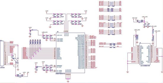
We are using DS90CF384AMTD ic in our one of the converter (LVDS to TTL 18 bit)  board. We are observing one strange behavior with this IC, when the board is powered up and there is no LVDS input, output starts showing white screen with colored lines on LCD panel even after asserting  /PWRDWN pin. Also, if we plug out the LVDS input while the system is running, the output retains the last display and after a delay it shows white screen with coloured lines. This patterns changes nearly every time.

As per our assumption, the LCD should show black/blank screen in case of no input. 

The same design is working with DS90CF584MTD IC with desired output. 

Please help me.          

Regards,

Shailendra Singh 

  • I think the behavior is most likely due to how your panel deals with no signal.

  • Greetings -

    As Ross noted, this is usually a setting in the TCON device on how it responds to unexpected timing.  There are some differences on how various LVDS DES respond to open inputs.  As just noted usually the TCON will detect the random timing and block it from reaching the panel.  The device noted has a PLL in it and with no inputs applied, it could be switching on the presense of noise and generating the random outputs.  A possible solution if the TCON cant block it would be to try adding a high impedance pull up to the LVDS CLK input (plus) to VCC, and a Pull down on the minus input to GND.  Perhaps try 1k Ohm.  This will likely make the LVDS CLK strap to a stable state, and prevent nosie from passing.  Some of the older / other LVDS DES have a different approach to the PLL blocks and may be more robust to switching on noise. 

    When the PWRDOWN pin is asserted all DES outputs are LOW (static), if noise is still seen on the panel, this is another sign of a TCON devicve setting or unusual operation.

    John Goldie

    DPS APPS / SVA

  • Hi John Goldie,

    Thanks for your help. I will try suggested changes in my design and update you with the result.

    BR,

    Shailendra Singh 

  • Hi John Goldie,

    The above solution did not worked for me, still getting same output on my tft panel.

    I am using Primeview PD064VT5 TFT LCD panel.  Below is the snap of my design, Kindly guide me. 


     Thanks,

    Shailendra Singh 

  • Greetings -

    From what I could see in the schematic, looks to be a correct connection to the DES.  I am concerned that your statement of asserting the PWRB signal did not change this problem.  That tells me that by setting the PWRB pin low, the DES outputs go to a LOW, and the probelm still occurs.  This indicates a probelm in how the TCON is responding to the no input case.  Register settings / firmware should be reviewed on that device to root cause the probelm.  I assume also the same TCON is used in the older and current design?

    These are more along guesses at this point, but you could also try:

    a) adjust the failsafe resistors (pull up and down) to a smaller value for strong bias, 750 Ohm for example.

    b) try related part - DS90CF384MTD - this one acts more like the older DS90CF584 that you reported as OK. 

    c) repeat the PWDB test and verifty outputs and clock are stable.

    John Goldie
    DPS APPS / SVA


  • hi

    i use ds90c385a for convert lvttl to lvds for panel 1366*768 lg ,i creat pattern mono color sample red green or blue , for example create red pattern I am concerned (R0.......R7) =3.3 steady state high  and

    (g0,g1 ,.....g7)=0     (b0....b7)=0   , clock 80 mhz , EN=steady state high  ,VSYNC=steady state high  ,HSYNC=steady state high  ,RES=steady state LOW ,POWERDOWN=steady state high  , but i could not see pattern on lcd   AND LVDS SIGNAL ON THE OUT PUT ONLY CLOCK SHIFT TO OUT PUT

    please help me BY SEND SHEMATIC CIRCUIT DETAIL PIN CONNECT

    TANKS

  • hi

    i use ds90c385a for convert lvttl to lvds for panel 1366*768 lg ,i creat pattern mono color sample red green or blue , for example create red pattern I am concerned (R0.......R7) =3.3 steady state high  and

    (g0,g1 ,.....g7)=0     (b0....b7)=0   , clock 80 mhz , EN=steady state high  ,VSYNC=steady state high  ,HSYNC=steady state high  ,RES=steady state LOW ,POWERDOWN=steady state high  , but i could not see pattern on lcd   AND LVDS SIGNAL ON THE OUT PUT ONLY CLOCK SHIFT TO OUT PUT

    please help me BY SEND SHEMATIC CIRCUIT DETAIL PIN CONNECT

  • please help me

  • Hi Reza,

    In order to drive the lcd display, you need to supply the proper video timing (Vsync, Hsync, DE) according the display’s specifications. The video sync signals cannot be steady state High. In your case, using a 1366x768 the DE pulse should be active every 1366 frames and 768 lines.

    Dac Tran

    SVA APPS

  • hi dac tran 

    tanks to reply 

    i read datasheet dc90c385 . in datasheet  to creat 64 gray scale  hsync vsync and .en =high 

    and i high thease signal! 

  • Hi Reza,

    The 16 grayscale test pattern (Fig 3) you are referring to in the DS90C385A datasheet is only a test pattern and does not represent actual display timing. Typically the panel datasheet will specific the required input display timings. Do you have the datasheet for LG panel? Is it a DE only panel? It should be listed under timing table with horizontal, vertical, and blanking specifications.

    Dac  Tran

    SVA APPS

  • hi dear dac tran 

    tanks for answer my question .

    i read lg display data sheet , please get me emails until send  for u  datasheet panel .

    very very tank you 

  • Hi Reza,

    Please email me directly dac (dot) tran (at) ti (dot) com