This thread has been locked.

If you have a related question, please click the "Ask a related question" button in the top right corner. The newly created question will be automatically linked to this question.

DS280DF810: Follow up the 25Gbps can't link up issue

Part Number: DS280DF810

Hi Expert and team,

I'm writing to follow up this E2E thread:https://e2e.ti.com/support/interface-group/interface/f/interface-forum/1599489/ds280df810-ds280df810-issue-follow-up/6173465

Customer discovered that they could not link up in another experiment, so they planned such a test. There are a few questions to ask for your help:

Customer Test Flow:
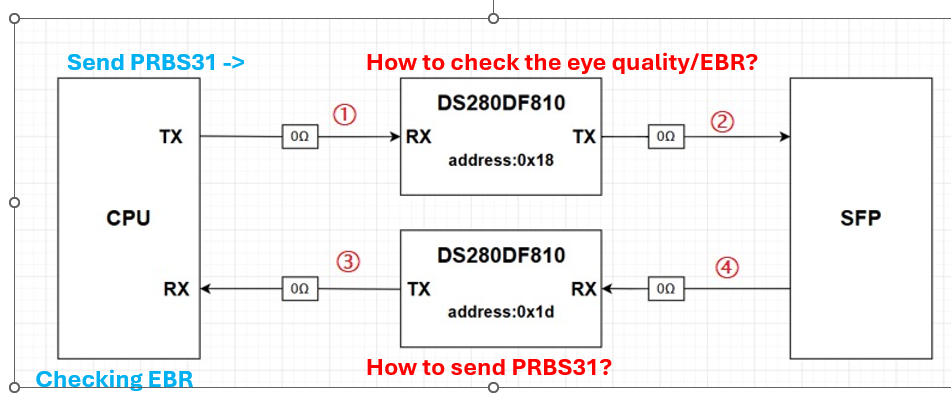
image.png

RX path: CPU sends PRBS31 and adjust its paramters. So, the DF810 need to measure the EBR as RX. I see in the porgramming guide that DF810 can read the PRBS checker and eye opeing parameter. 

Can customers read these registers as FoM to adjust parameters like FFE, pre-cursor, post-cursor for CPU TX side? Does that make sense?

Also, dis there a mapping of the value of the HEO/VEO and the quality of the eye? What the values of HEO and VEO registers are, means that the eye opening is good?
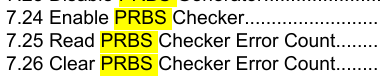
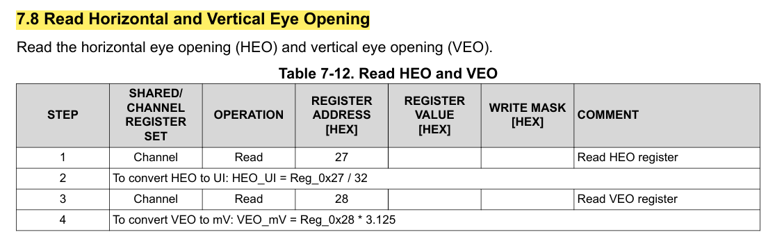
image.png

image.png

TX path: DF810 send PRBS31 to CPU and adjust the parameter like CTLE, DFE and pre-/post- cursor, and then CPU check the FoM... So, DF810 need to generate PRBS and adjust the parameters. I noticed that in programming guide, pre-/post-/main- cursor can be set in Table5-4/ Table7-17.  Also, the PRBS generator can be enabled in 7.22 and 7.23. Customer can use these register to impement the test. Does that make sense?

BTW, as DF810 can enable adaptive CTLE and DFE, in addition to these two parameters and pre/post/main cursor, what other parameters need to be manually adjusted by the customer? 

image.png

 image.png

BRs,

Rannie

  • Hi Rannie,

    RX path:

    Your understanding here is correct.  The customer can use the retimer prbs check and eye opening as FoM to optimize CPU TX settings.  We actually have an application note discussing this, please see below.

    Please also keep in mind that each time a new CPU TX setting is tested, the retimer should re-adapt to the signal.  To trigger re-adaptation, customer can do CDR reset on the retimer.

    https://www.ti.com/lit/an/slyt678/slyt678.pdf

    TX path:

    DF810 send PRBS31 to CPU and adjust the parameter like CTLE, DFE and pre-/post- cursor, and then CPU check the FoM... So, DF810 need to generate PRBS and adjust the parameters. I noticed that in programming guide, pre-/post-/main- cursor can be set in Table5-4/ Table7-17.  Also, the PRBS generator can be enabled in 7.22 and 7.23. Customer can use these register to impement the test. Does that make sense?

    Please confirm my understanding below is correct.  This procedure (as summarized below) makes sense.

    • On DS280DF810, customer plans to enable PRBS generator and try different pre/main/post values
      • Note DS280DF810 requires CDR lock to enable PRBS generator.  Customer will need to provide signal to DS280DF810 for it to acquire CDR lock.
    • On CPU, customer will adjust RX equalization parameters like CTLE and DFE and check FoM in order to identify best DS280DF810 TX settings.

    BTW, as DF810 can enable adaptive CTLE and DFE, in addition to these two parameters and pre/post/main cursor, what other parameters need to be manually adjusted by the customer? 

    The key parameters that customers need to tune are adapt mode and TX settings (pre/main/post cursor).  Depending on signal amplitude, sometimes customers also need to adjust RX DC gain.  See "7.32 Set Variable Gain Amplifier (VGA) and CTLE DC Gain Mode".

    FYI, there are a few other parameters that customers can typically leave at default, but sometimes we adjust these during debug:

    • CDR bandwidth
    • EOM timer

    i think customer can work on setting adapt mode and TX settings before trying advanced adjustments.  Please let us know if customer runs into challenges with their testing.

    Thanks,

    Drew

  • Hi Drew,

    Thanks for your kindly reply.

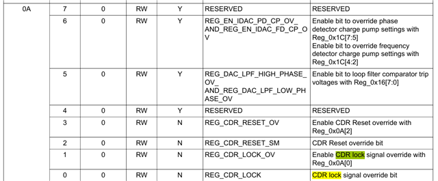
    For PRBS generator, customer writing below registers but no PRBS31 waveform from DF810. Can you help to check is there any other register need to configure? Especially how to "provide signal to DS280DF810 for it to acquire CDR lock."? Should customer set 0x0A bit[0] and bit[1]?

    Customer feedback that there is still no PRBS signal if adding 0x0A 0x03 0x03 to enable CDR lock. They also read the 0x78 bit[4] = "1", which indicates the CDR are locked.

    "0xFF 0x01" channel mode

    "0xFC 0x01" select Chanel0

    "0x0A 0x03 0x03" * if setting 0x0A bit [0] [1] [3] to "1", the device still can't output PRBS31.

    "0x2E 0x04 0x04" #set prbs31

    "0x30 0x01 0x03" #set prbs31 mode

    "0x1E 0x10 0x10" #open 

    "0x79 0x20 0x20"# enable Generator

    "0x30 0x08 0x08" #enable clock

    "0xA5 0x20 0x38" #prbs output

    BRs,

    Rannie

  • Hi Rannie,

    Following up on our Webex discussion, for PRBS generator to work on DS280DF810, the device requires CDR lock.

    Customer can accomplish this through external loopback, as you suggested.

    Thanks,

    Drew

  • Hi Drew,

    Thanks for your reply.

    Customers use the adjacent SFP interface loopback, they can output PRBS31 pattern, and on the CPU side they see the eye parameters are very poor, so they tune pre-/post-/main-cursor by table7-17. It is found link down and the eye diagram can not be read. Why does the CPU side not read the eye diagram and no waveforms are sent out when the customer executes the following command?

    customer tried below value for pre- post- and main- cursor:

    08 08 10: can't read the eye pattern parameter and link down, 

    00 00 00: can read the pattern but the quality is bad, link down occasionally.

    BRs,

    Rannie

  • Hi Drew,

    Update today test (2/2):

    The default value of 3D~3F read by the customer is:

    3D:0x1A; 3E: 0x40; 3F: 0x40

    The range in datasheet is:

    It seems that the default value exceeds the range in datasheet. But according to the mask value, only bit[0] ~[4] are considered, this default value make sense.

    So, customer write 3D to adjust the eye height. They adjusted 3D from 0x1A (default value) to the maximum value (0x1F) and eye height was 35 and still could not meet the requirement (60). Is there any direction to adjust next? Are there other parameters that can be adjusted? Looking forward to your reply.

    BRs,

    Rannie

  • Hi Rannie,

    eye height was 35 and still could not meet the requirement (60

    To clarify, is this CPU requirement?

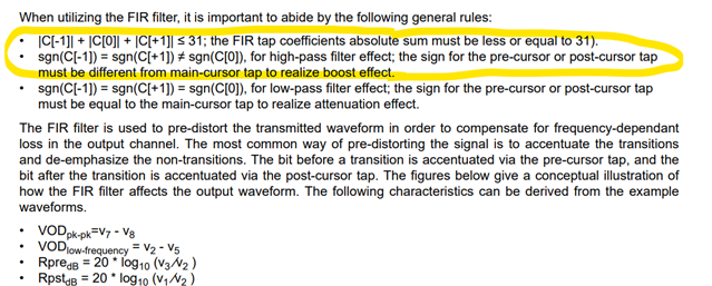
    From data sheet, the sum of absolute values of pre, main, and post cursor should not exceed 31.  Customer should try adding some pre and post cursor boost.  In order to do this, they should maintain constant sum of pre, main, and post.  For example, if customer starts with pre=0, main=31, post=0, customer could try pre = -1, main = 30, post = 0.

    The best settings at 25G typically involve some amount of pre and post cursor.  For example, pre = -3, main = 23, post = -5.  The actual best values are dependent on the channel and the receiver equalizer.

    Thanks,

    Drew

  • Hi Drew,

    Customer tried pre=-3, post=-5, main=23, the eye pattern becomes worse than main=0x1F, pre=post=0. They also tried reset CPU RX auto adaptive after changing FIR parameters, but the eye pattern has no change. 

    Can you provide any directions to improve the FIR parameters? Customer IS from DF810 to CPU_RX is 6.3dB.

    BRs,

    Rannie

  • Hi Rannie,

    Customer should sweep pre/main/post to identify best values.

    Also, what is minimum EQ on CPU.  Is there any chance signal is being over equalized?

    Thanks,

    Drew