This thread has been locked.

If you have a related question, please click the "Ask a related question" button in the top right corner. The newly created question will be automatically linked to this question.

AM69A: AM69A cannot recognize the TUSB 8044 chip.

Part Number: AM69A
Other Parts Discussed in Thread: AM69, TUSB8041, TUSB8044, TUSB8044AEVM

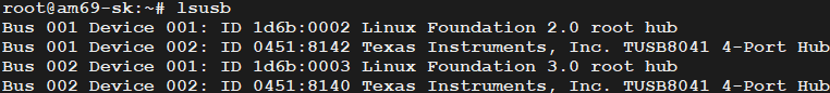
We can see the TUSB8041 on the EVM, as shown in the image below.

image.png

And then, insert the same SD card into our board.
However, on our own board, 
we use the TUSB 8044(TI_TUSB8044AIRGCT),
but we can't see the TUSB 8044 ,
as shown in the image below.


image.png

We tried connecting a USB flash drive, mouse, and keyboard, 
but there was no response or message.
We also couldn't see any messages using dmesg.

How can I solve the problem of USB not working?
  • Please see the important notice on support for AM69 family 

    [FAQ] Important Notice for Support transition for AM68/AM68A and AM69/AM69A devices - Processors forum - Processors - TI E2E support forums

    Here are some tips that may help , as this sounds like a hardware problem in your board 

    The TUSB8044 not being detected on your custom board is likely due to hardware configuration issues, particularly with the I²C EEPROM configuration, clock circuitry, power supply design, or strap pin settings that differ from the working TUSB8041 EVM reference design.

    Helper Tips 

    Critical Configuration Requirements

    The TUSB8044 will not connect to the upstream port until its configuration is complete [1]. This is a fundamental difference from some other USB hubs and is the most likely cause of your device not appearing in the system. The configuration process depends on several hardware elements that must be correctly implemented.

    I²C EEPROM Configuration

    If your board uses an I²C EEPROM for configuration, verify the following:

    • The TUSB8044 only loads configuration registers if the EEPROM contents at address byte 00h equals 55h [1]
    • If the first byte is not 55h, the device exits I²C mode and continues with default values [1]
    • The external configuration interface is enabled when both SCL/SMBCLK and SDA/SMBDAT pins are pulled up to 3.3V at reset de-assertion [1]
    • The mode (I²C master or SMBus slave) is determined by the SMBUSz/SS_SUSPEND pin state at reset [1]
    • Minimum EEPROM size required is 8Kbit [1]

    Clock Circuit Verification

    The clock circuit is critical for proper operation. Verify your implementation matches these requirements:

    Crystal Configuration:

    • Requires a 24-MHz low-ESR crystal with a 1-MΩ feedback resistor between XI (Pin 62) and XO (Pin 61) pins [2][3]
    • Crystal must operate in fundamental mode with load capacitance of 12 to 24 pF [3][4]
    • Frequency stability must be ±100 PPM or better [3][4]
    • Maximum crystal equivalent series resistance (ESR) is 50Ω [3][4]

    Alternative Clock Source: If using an external oscillator instead of a crystal:

    • Must have ±100 PPM (or better) frequency stability [3][4]
    • Must have less than 50-ps absolute peak-to-peak jitter [3][4]

    Power Supply Configuration

    USB_R1 Precision Resistor:

    • Pin 64 requires a 9.53-kΩ ±1% precision resistor connected between it and GND [2]

    VBUS Monitoring: VBUS cannot be directly connected to the TUSB8044 device [4]. It requires proper filtering:

    • USB_VBUS pin (Pin 48) must be connected to VBUS through a 90.9-kΩ ±1% resistor [2][4]
    • Must be connected to ground through a 10-kΩ ±1% resistor [2][4]
    • A bulk capacitor of at least 1 µF is required on the upstream port VBUS input [3][4]
    • The TUSB8044 EVM uses a 10-µF capacitor for this purpose [3][4]

    Self-Powered Hub Configuration:

    • The TUSB8044 on the EVM is configured as a self-powered hub [3]
    • Downstream port VBUS is typically provided by external 5V power, not from the upstream host [3]
    • Overcurrent events on downstream ports are reported through OVERCURxZ inputs [3]

    Reset Configuration

    The GRSTz pin (Pin 50) is the global power reset [2]. When this pin is asserted low, the device is completely nonfunctional [2]. Ensure this pin is in a high state for the device to operate.

    Port Configuration Strap Pins

    The TUSB8044 uses hardware strap pins to configure port functionality. Verify your board's USED[3:0], RMBL[3:0], and USB2_ONLY[3:0] configurations match one of the valid modes [5]:

    USED[3:0]
    RMBL[3:0]
    USB2_ONLY[3:0]
    Configuration
    1111
    1111
    0000
    4 Port USB 3.2 Hub, 6 Port USB2.0 Hub
    1110
    1111
    0000
    3 Port USB 3.2 Hub, 5 Port USB2.0 Hub
    1100
    0111
    0000
    2 Port USB 3.2 Hub, 4 Port USB2.0 Hub
    0011
    1111
    0010
    1 Port USB 3.2 Hub, 4 Port USB 2.0 Hub
    1000
    1111
    0010
    1 Port USB 3.2 Hub, 4 Port USB 2.0 Hub
    1111
    1111
    1110
    1 Port USB 3.2 Hub, 6 Port USB 2.0 Hub

    Invalid strap pin combinations will prevent proper device enumeration [5].

    USB Signal Polarity

    If the DM/DP signal lines are swapped on your custom PCB layout, the device will not function [6][7]. The TUSB8044 provides a USB 2.0 Port Polarity Control Register (Offset Bh) to correct for layout swaps:

    To Configure Polarity:

    1. Set the customPolarity bit (bit 7 of register Bh) to '1' to enable write access [6][7]
    2. Set the corresponding port polarity bits:
      • p0_usb2pol for upstream port
      • p1_usb2pol through p4_usb2pol for downstream ports 1-4
    3. Setting a bit to '1' swaps the polarity (DM becomes DP, and DP becomes DM) [6][7]

    By default, all polarity bits are '0' (not swapped) and read-only from internal OTP ROM [7].

    Reference Design Comparison

    The TUSB8044AEVM evaluation module acts as a hardware reference design [8]. Compare your custom board schematic against the EVM schematics in Appendix B of the user guide [8]. Pay particular attention to:

    • Switch settings for configuration mode (strap vs. SMBus) [9]
    • Port power control settings (ganged vs. individual mode) [9]
    • Port enable/disable configurations [9]

    Recommended Troubleshooting Steps

    1. Verify Reset: Confirm GRSTz pin is high during operation
    2. Check Clock: Measure the 24-MHz clock signal at XI/XO pins with an oscilloscope
    3. Verify Power: Measure voltages on USB_VBUS and USB_R1 pins
    4. Check EEPROM: If using I²C EEPROM, verify the first byte is 55h
    5. Validate Strap Pins: Measure USED[3:0], RMBL[3:0], and USB2_ONLY[3:0] pin states
    6. Compare to Reference: Cross-reference your design with the TUSB8044AEVM schematics
    7. Check Signal Polarity: Verify DM/DP routing matches the reference design or configure polarity register if swapped

    Citations

    1. TUSB8044 Configuration Requirements - Datasheet Section 7.3.5.1
    2. TUSB8044 Pin Functions and Critical Hardware Requirements - Datasheet Section 5
    3. TUSB8044RGC EVM Hardware Overview - Clock and Power Design
    4. TUSB8044AEVM Hardware Requirements - User Guide Section 2
    5. TUSB8044A Downstream Port Configuration Examples - Datasheet Table 7-6
    6. USB 2.0 Port Polarity Control Register - TUSB8044A Datasheet
    7. USB 2.0 Port Polarity Control - TUSB8044 Datasheet Section 7.6
    8. TUSB8044AEVM as Hardware Reference Design - User Guide Section 1
    9. TUSB8041EVM Switch Configuration Reference - User Guide Table 1