DS160PR410: Different Combination to Achieve x2 structure.

Part Number: DS160PR410

Hi TI Expert.

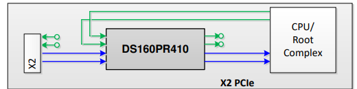
When we try to achieve two x2 structure, we can use 4ch on single IC with total 2 ICs.

image.png

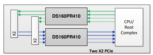
Or using 2 Lane on each IC with total 2 ICs, similar to below connection.

image.png


Looks like both of the combination can achieve the function we need.

But wondering what would be the Pros & Cons of them.

Based on your experience, could you share with us what would be the best way to achieve that and the reason behind it?


Thank you.


  • Hi Evan,

    DS160PR410 is a unidirectional redriver. As you pointed out, there are two potential redriver configurations for 4 channels:
    1. Unidirectional, one redriver handles x4 upstream (endpoint to root complex), one redriver handles x4 downstream (root complex to endpoint)
    2. Bidirectional, each redriver handles x2 upstream x2 downstream for a total of 4 channels.

    The key consideration to choose between these two are signal integrity and redriver placement. The intricacies are detailed in snla461. I will give a brief summary here:

    • A redriver performs best when compensating for signal degradation that has happened before entering the RX inputs. The redriver only needs to boost the degraded signal back to normal levels so the final receiver can see a good signal.
    • In some cases, a redriver can be placed where there is relatively large loss in front of the redriver TX output. In this case, the redriver can be tuned to over-equalize the signal so that the post-redriver channel loss will normalize the signal at the reciever. This process is not as clean as equalizing pre-redriver loss. High amounts of over-equalization may result in distortion that doesn't properly roll off.

    Therefore, proper placement of the redriver is needed to balance the difference in performance of equalization compared to over-equalization.

    Regarding Customer's case: 

    In Case 1 above: Upstream redriver can be placed closed to the Root Complex and downstream redriver can be placed close to endpoint. Thus the majority of the loss is placed before the redriver RX-input for the best performance.

    In Case 2 above: Redriver should be placed in the middle of the channel's loss so that both directions have similar performance. However, as your diagram shows, one direction's channel will need vias which will add impedance discontinuities and cause potential signal integrity challenges.

    The benefit to case 2 is that if customer is using a single x2 endpoint, only 1 redriver is needed, saving on BOM cost. If customer is using more than a single x2 endpoint, Case 1 should offer better performance.

    Please have customer perform signal integrity simulations with our device IBIS-AMI models to verify the PCB layout is optimized.

    Best,

    Charles