This thread has been locked.

If you have a related question, please click the "Ask a related question" button in the top right corner. The newly created question will be automatically linked to this question.

DP83822I: DP83822I - LVPECL / 100BASE-FX termination & biasing guidance for external fiber transceiver (AC-coupled)

Part Number: DP83822I
Other Parts Discussed in Thread: DP83822EVM

Hello TI Support Team,

I am Kai Yang Eng, an Application Engineer at Broadcom supporting Industrial Fiber Optic transceivers. We are currently supporting a customer design using the TI DP83822I (100BASE-FX) connected to an external fiber-optic transceiver with LVPECL differential interface (Broadcom transceiver AFBR-59E5APZ). The customer experiences a functional issue with the transceiver. We suspect the root cause may be related to incorrect LVPECL termination / biasing / AC-coupling around the DP83822I differential I/O.

We need TI’s guidance to confirm the recommended DP83822I hardware interface for LVPECL in 100BASE-FX mode:

  1. DP83822I differential I/O electrical expectations
    • Are the DP83822I FX differential pins intended to be used as LVPECL?
    • What are the expected common-mode requirements, signal swing, and internal biasing/termination assumptions (if any)?
  2. Recommended termination / bias network
    • For AC-coupled connection to an external LVPECL transceiver (which already integrates AC-coupling capacitors and internal termination on the module side), what external termination/biasing is required on the DP83822I side?
    • Is a 100 Ohms differential termination across the pair at the DP83822I pins recommended?
    • Are 50 Ohms pull-ups to 3.3 V recommended/allowed for DP83822I LVPECL termination? (In our review, this looks unusual and may cause incorrect common-mode or double termination.)
  3. Placement guidance
    • If external termination is required: should it be near the DP83822I pins (receiver/PHY side), or near the transceiver?
  4. Documentation request
    • The DP83822I datasheet does not clearly describe the differential I/O termination options for this LVPECL use case. If there is an application note, layout guideline, or reference design specifically for DP83822I + 100BASE-FX + LVPECL termination, please point us to the correct TI reference.


Thank you for your support and any recommended schematics / calculations to ensure DP83822I compatibility with LVPECL external transceivers in 100BASE-FX mode.

Best regards,
Kai Yang Eng
Application Engineer, Broadcom

  • Hi Kai,

    1. DP83822 FX pins use current mode drivers to generate LVDS for a connected fiber transceiver module. If your LVPECL transceiver accepts 100Base-X signaling then it should be compatible with DP83822

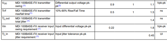
    • Relevant electrical specs on the FX pins are noted in the Electrical Characteristics section of the datasheet:

    2. If your transceiver integrates the terminations shown in the datasheet already then you would not need external terminations. Please double check that there are appropriate pullups and capacitors integrated in the transceiver. You may want to follow the example in this related E2E for reference.

    • A 100Ohm differential termination is not needed. You only need the shown 50 ohm pullup. This pullup is required as without it the current mode driver within DP83822 will not work.

    3. External terminations can be near the PHY or near the transceiver. I'd recommend placing these around the middle of the signal path between PHY and transceiver.

    4. I don't believe we have a reference design, but the DP83822EVM has example LVPECL terminations. I'd recommend looking at the schematic in the user's guide to get an idea of how these should look:

    Best,

    Shane

  • Hi Shane,

    Thanks for the clarification. To support our customer design review, could you please help us with a few follow-up details specifically for DP83822I/DP83822I(F) in 100BASE-FX mode (FX pins, datasheet pins 9-12)?

    1. In 100Base-FX mode, what is the internal termination (components and reference level to GND/Vcc) of pins 9-12? What type of output/input is it in BASE-FX mode?
    2. Can the termination change depending on the selected operating mode (e.g., open-drain needing pull-ups, AC-coupled signal with internal coupling caps, internal pullups/pulldowns)?
    3. Is the PHY transmitter output swing selectable to adjust the PHY to the needs of a specific fiber transmitter?
    4. The acceptable amplitude swing on the PHY receiver side: is it really 0.22V to 1.8 Vpp (differential)? what is the recommended swing for best / more reliable performance?
    5. Our transceiver module integrates AC-coupling and termination on the module side. Could you please help to check what would be the recommended PHY termination when operating it with our TRX "AFBR-59E5APZ". Please find the attached transceiver DS below.

    2543.AFBR-59E5APZ-DS101.pdf

    Best regards,

    Kai Yang Eng

    Application Engineer, Broadcom
  • Hi Kai,

    1. Pins 9-12 are current mode drivers in 100Base-FX mode. The termination components and reference level are the external 50 ohm pullups to the 3.3V rail.

    2. The termination should remain constant.

    3.  Yes, register 0x0403 can adjust the 100Base-FX signal swing as shown in the datasheet:

    4. Yes that is the correct range for fiber receivers. I recommend keeping some margin on these bounds for the most reliable performance.

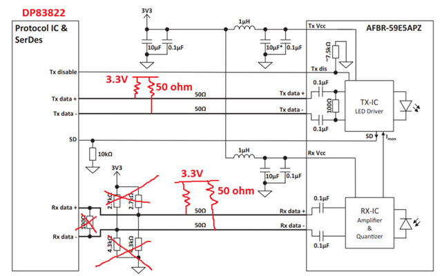
    5. Looking at the module you've linked I sketched what I believe would be the correct termination scheme:

    • In this case, I recommend trying your module with the DP83822EVM to validate the use-case. This EVM has space for an SFP cage that can be mounted on the board. There are also spaces for terminations on the TX/RX fiber lines. Are you able to evaluate with this board beforehand?

    Best,

    Shane