


Part Number: DP83825I
Hi,
we have used the DP83825IRMQR part in one of our device requiring 10/100Mbps network connection.
We faced the below mentioned issue in 2 out of the 30 numbers of PCB developed by us with this PHY IC . Attaching the schematics of the design.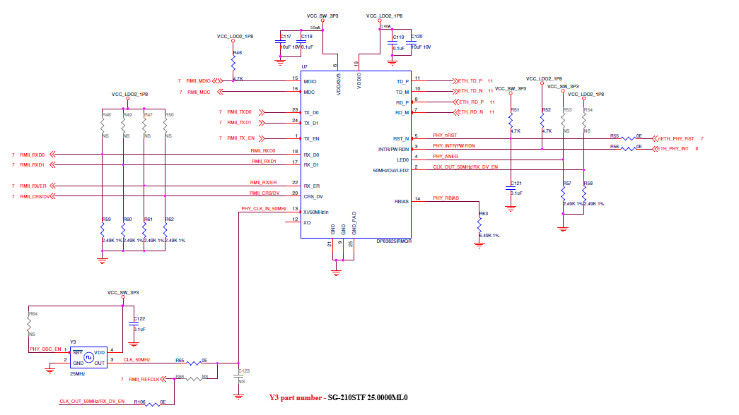
Issue :
- The device was not able to function in the 100Mbps mode.
- We used the same firmware and the same support accessories for testing ( laptops , ethernet cables) as in the working boards.
Observations :
- The device link is re-established and the works properly when forced to 10Mbps mode, but not working when forced to 100Mbps mode.
- The power sequence , voltage levels and reset sequence has all been validated in the boards and the parameters seems to be in accordance with the recommended values.
- The clock signals were probed and found to be good and well at 25MHz
- We tried changing the oscillator as mentioned in this forum : but was not successful. - https://e2e.ti.com/support/interface-group/interface/f/interface-forum/1588099/dp83825i-unable-to-establish-100mbps-link-with-dp83825i-ethernet-phy
- We tried loopback test in all the modes ( from MAC till the ethernet cable) - All the loopback results showed success in the 100Mbps link.
- Reset timing and tuning was tried out by introducing additional delay - did not resolve the issue.
- Tried swapping the PHY IC between a working and non working board - the issue still repeats ( the working board turned non working ) ; hence proving that the issue was within the PHY IC )
We were able to resolve the issue when the non-working IC was replaced by a fresh PHY sample.
Please share your comments on the same.
