Part Number: TCAN1145EVM
Other Parts Discussed in Thread: TCAN1145-Q1
We are using the TCAN1145-Q1 in our project and have observed a reproducible behavior during testing that appears to be related to the device’s power thresholds and internal state machine. Specifically, when Vcc is briefly pulled to 0 V (intentionally creating an UVcc condition) while Vsup remains present, whether the device can be switched to Normal mode via SPI immediately afterward depends on whether Vsup drops below the recovery / power-on threshold (Uv_sup) during this process.
We have reviewed the publicly available datasheet, but we are still unable to determine the exact cause behind this behavior, especially regarding the following questions:
- What is the internal difference in device state between:
- Vcc drops but Vsup does not fall below its threshold, and
- Vcc drops and Vsup also falls below its threshold?
- In the case where Vcc drops but Vsup does not fall below its threshold, why is the device unable to switch to Normal mode via SPI, even though writes and readbacks to the MODE_CNTRL register are successful?
- In the case where Vcc drops and Vsup falls below the threshold and then recovers, why can the same SPI command to switch to Normal mode take effect immediately after Vcc is restored, even though the register behavior is identical to the previous case?
- Is there any internal state machine protection logic or fault latch mechanism not explicitly described in the datasheet that could explain the behavior?
We kindly request your assistance in confirming whether the above observations are consistent with the intended device design and to provide further technical clarification.
Test Environment
- Device: TCAN1145
- Power and interfaces:
- Vsup: Lab power supply, nominal 12 V (pulled down & restored per test steps)
- Vcc: 5 V LDO, includes intentional drop to 0 V and recovery
- Vio: MCU 3.3 V IO rail
- SPI Host: TC332, CLK = 2.4 MHz
Two test sequences with different outcomes
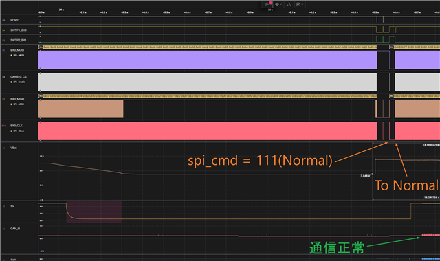
A) Vsup pulled down to 3.8 V and then raised to 8 V → Able to switch to Normal immediately
(Refer to attachment: 3.84v_ok.png)
- Initial state: Normal mode (VSUP=12 V, VCC=5 V, VIO=3.3 V, transceiver=Normal).
- Pull VCC to 0 V (create UVcc).
- Pull VSUP down to 3.8 V, then lift to 8 V — this appears to trigger a “fast power-on/Standby transition.”
- Write
MODE_SEL = Normalvia SPI; register write and readback both successful. - Restore VCC to 5 V → the device immediately enters Normal mode when UVcc clears.
B) Vsup pulled down only to 4.58 V, then raised to 10 V → Immediate Normal-mode switching fails
(Refer to attachment: 4.58v_KeepSleep.png)
- Initial state: Normal mode (VSUP=12 V, VCC=5 V, VIO=3.3 V, transceiver=Normal).
- Pull VCC to 0 V (create UVcc).
- Pull VSUP to 4.58 V, then raise to 10 V.
- Write
MODE_SEL = Normalvia SPI; register write and readback are successful. - Restore VCC to 5 V → transceiver remains in Sleep mode and does not communicate.
- Writing
MODE_SEL = Normalagain transitions the device to Normal mode, and communication works normally.