This thread has been locked.

If you have a related question, please click the "Ask a related question" button in the top right corner. The newly created question will be automatically linked to this question.

DS90UB954-Q1: Image capture doesn't work for 4 lanes DS90UB953 - DS90UB954

Part Number: DS90UB954-Q1

Hello everyone.
We have a camera kit: imx412 -> DS90UB953 -> DS90UB954
the DS90UB954 is connected to a MIPI Jetson Orin NX.
We set up the channel using 2 lanes, and everything works fine.

But after making changes and switching to 4 lanes, we can't get an image.
The capture works, but the image appears as noise, occupying a quarter of the screen.
We tested the ability to capture 4 lanes from a camera connected directly to MIPI.
Everything works.
So, the question is about the DS90UB953->DS90UB954 connection.

We checked the registers that configure the serializer and deserializer lines.
Below are the dumps of these registers.

Please tell me what register settings need to be adjusted to get 4 lanes.

Only the second channel of the DS90UB954 is used for testing.


[19:27:47.624] 954-:DEVICE_STS              [0x04]=0xDF
[19:27:47.624] 954-:CSI_CTL                 [0x33]=0x43
[19:27:47.624] 954-:CSI_CTL2                [0x34]=0x40
[19:27:47.625] 954-:FWD_CTL1                [0x20]=0x10
[19:27:47.625] 954-:FWD_CTL2                [0x21]=0x01
[19:27:47.626] 954-:CSI_PLL_CTL             [0x1F]=0x00
[19:27:47.626] 954-:PORT_CONFIG             [0x6D]=0x7C
[19:27:47.627] 954-:PAR_ERR_THOLD_HI        [0x05]=0x01
[19:27:47.627] 954-:PAR_ERR_THOLD_LO        [0x06]=0x00
[19:27:47.627] 954-:RX_PORT_STS1            [0x4D]=0x43
[19:27:47.628] 954-:RX_PORT_STS2            [0x4E]=0x1C
[19:27:47.628] 954-:RX_PAR_ERR_HI           [0x55]=0x00
[19:27:47.628] 954-:RX_PAR_ERR_LO           [0x56]=0x00
[19:27:47.629] 954-:CSI_RX_STS              [0x7A]=0x0C
[19:27:47.629] 954-:CSI_ERR_COUNTER         [0x7B]=0xFF
[19:27:47.629] 954-:LINK_ERROR_COUNT        [0xB9]=0x33
[19:27:47.630] 954-:PORT_DEBUG              [0xD0]=0x00
[19:27:47.630] 954-:INTERRUPT_STS           [0x24]=0x00
[19:27:47.630] 954-:CSI_TX_ICR              [0x36]=0x00
[19:27:47.631] 954-:CSI_STS                 [0x35]=0x01
[19:27:47.631] 954-:CSI_TX_ISR              [0x37]=0x03
[19:27:47.632] 954-:PORT_ICR_HI             [0xD8]=0x00
[19:27:47.632] 954-:PORT_ICR_LO             [0xD9]=0x00
[19:27:47.632] 954-:PORT_ISR_HI             [0xDA]=0x00
[19:27:47.633] 954-:PORT_ISR_LO             [0xDB]=0x18


[19:27:47.634] 953-:RESET_CTL               [0x01]=0x00
[19:27:47.635] 953-:General_CFG             [0x02]=0x73
[19:27:47.635] 953-:MODE_SEL                [0x03]=0x48
[19:27:47.636] 953-:CSI_POL_SEL             [0x20]=0x00
[19:27:47.636] 953-:CSI_LP_POLARITY         [0x21]=0x00
[19:27:47.636] 953-:CSI_EN_HSRX             [0x22]=0x00
[19:27:47.637] 953-:CSI_EN_LPRX             [0x23]=0x00
[19:27:47.637] 953-:CSI_EN_RXTERM           [0x24]=0x00
[19:27:47.637] 953-:CSI_PKT_HDR_TINIT_CTRL  [0x31]=0x20
[19:27:47.637] 953-:DEVICE_ID               [0x00]=0x32
[19:27:47.638] 953-:BC_CTRL                 [0x49]=0x00
[19:27:47.641] 953-:GENERAL_STATUS          [0x52]=0x65
[19:27:47.642] 953-:BIST_ERR_CNT            [0x54]=0x00
[19:27:47.642] 953-:CRC_ERR_CNT1            [0x55]=0x00
[19:27:47.642] 953-:CRC_ERR_CNT2            [0x56]=0x00
[19:27:47.642] 953-:CSI_ERR_CNT             [0x5C]=0x00
[19:27:47.643] 953-:CSI_ERR_STATUS          [0x5D]=0x00
[19:27:47.643] 953-:CSI_ERR_DLANE01         [0x5E]=0x00
[19:27:47.643] 953-:CSI_ERR_DLANE23         [0x5F]=0x00
[19:27:47.644] 953-:CSI_ERR_CLK_LANE        [0x60]=0x00

  • Hello Ivan,

    can you provide more details about the Image being sent by the image sensor, such as data type, resolution and frame rate?

    Also, what is the speed the image sensor is outputting data at? i.e. how many Mbps/lane?

  • Thank you so much for your reply.

    such as data type, resolution and frame rate?

    Image data from the imx412 camera
    RAW10 format
    Resolution 1920x1080
    Frame 60 FPS


    i.e. how many Mbps/lane?

    According to calculations, the overall speed is 1.485-1.85 Gbps
    Which corresponds to approximately 0.371-0.463 Gbps per line

  • Hi Ivan,

    From the provided register dumps I can see that the DES is reporting Buffer errors and CSI errors (length and checksum errors). The CSI error counter has the value of 0xFF which means all the received data is faulty.

    On the SER we can see BCC errors are being reported.

    Can you first test your DES using the Patgen and see if the display is showing normal.

    Next step to test with the SER Patgen and if the display is showing normal

  • Thank you so much for your reply.
    We tested Patgen and got a good image from the DS90UB954.
    Then we disabled Patgen on the DS90UB954 and ran it on the DS90UB953.
    And we also got a good result.

    Summary
    1. Patgen works with the serializer and we get a good image on 4 lanes.
    2. We have an imx412 camera connected to the DS90UB953 on 2 lanes.

    Problem
    Our imx412 camera connected to the DS90UB953 on 4 lanes doesn't work.

    Can we narrow the search to the imx412 -> DS90UB953 junction, excluding the DS90UB954?
    Maybe some specific settings are needed for the DS90UB953?

    Below is a dump of the registers when capturing the Patgen image, which is generated by DS90UB953.

    [01:55:23.502] 954-:DEVICE_STS              [0x04]=0xDF
    [01:55:23.502] 954-:CSI_CTL2                [0x34]=0x40
    [01:55:23.503] 954-:FWD_CTL1                [0x20]=0x10
    [01:55:23.503] 954-:FWD_CTL2                [0x21]=0x01
    [01:55:23.503] 954-:CSI_PLL_CTL             [0x1F]=0x00
    [01:55:23.503] 954-:PORT_CONFIG             [0x6D]=0x7C
    [01:55:23.504] 954-:PAR_ERR_THOLD_HI        [0x05]=0x01
    [01:55:23.504] 954-:PAR_ERR_THOLD_LO        [0x06]=0x00
    [01:55:23.504] 954-:RX_PORT_STS1            [0x4D]=0x43
    [01:55:23.504] 954-:RX_PORT_STS2            [0x4E]=0x4D
    [01:55:23.505] 954-:RX_PAR_ERR_HI           [0x55]=0x00
    [01:55:23.505] 954-:RX_PAR_ERR_LO           [0x56]=0x00
    [01:55:23.505] 954-:CSI_RX_STS              [0x7A]=0x0C
    [01:55:23.505] 954-:CSI_ERR_COUNTER         [0x7B]=0xFF
    [01:55:23.505] 954-:LINK_ERROR_COUNT        [0xB9]=0x33
    [01:55:23.506] 954-:PORT_DEBUG              [0xD0]=0x00
    [01:55:23.506] 954-:INTERRUPT_STS           [0x24]=0x00
    [01:55:23.506] 954-:CSI_TX_ICR              [0x36]=0x00
    [01:55:23.506] 954-:CSI_STS                 [0x35]=0x01
    [01:55:23.507] 954-:CSI_TX_ISR              [0x37]=0x03
    [01:55:23.507] 954-:PORT_ICR_HI             [0xD8]=0x00
    [01:55:23.507] 954-:PORT_ICR_LO             [0xD9]=0x00
    [01:55:23.507] 954-:PORT_ISR_HI             [0xDA]=0x00
    [01:55:23.507] 954-:PORT_ISR_LO             [0xDB]=0x00
    
    [01:55:23.508] 953-:RESET_CTL               [0x01]=0x00
    [01:55:23.508] 953-:General_CFG             [0x02]=0x73
    [01:55:23.508] 953-:MODE_SEL                [0x03]=0x48
    [01:55:23.508] 953-:CSI_POL_SEL             [0x20]=0x00
    [01:55:23.509] 953-:CSI_LP_POLARITY         [0x21]=0x00
    [01:55:23.509] 953-:CSI_EN_HSRX             [0x22]=0x00
    [01:55:23.509] 953-:CSI_EN_LPRX             [0x23]=0x00
    [01:55:23.509] 953-:CSI_EN_RXTERM           [0x24]=0x00
    [01:55:23.509] 953-:CSI_PKT_HDR_TINIT_CTRL  [0x31]=0x20
    [01:55:23.510] 953-:DEVICE_ID               [0x00]=0x32
    [01:55:23.510] 953-:BC_CTRL                 [0x49]=0x00
    [01:55:23.510] 953-:GENERAL_STATUS          [0x52]=0x65
    [01:55:23.510] 953-:BIST_ERR_CNT            [0x54]=0x00
    [01:55:23.511] 953-:CRC_ERR_CNT1            [0x55]=0x00
    [01:55:23.511] 953-:CRC_ERR_CNT2            [0x56]=0x00
    [01:55:23.511] 953-:CSI_ERR_CNT             [0x5C]=0x00
    [01:55:23.511] 953-:CSI_ERR_STATUS          [0x5D]=0x00
    [01:55:23.511] 953-:CSI_ERR_DLANE01         [0x5E]=0x00
    [01:55:23.512] 953-:CSI_ERR_DLANE23         [0x5F]=0x00
    [01:55:23.512] 953-:CSI_ERR_CLK_LANE        [0x60]=0x00
    

  • Hello Ivan,

    the new UB953 register dump values are exactly the same as the previous ones. Also I can see there is BCC CRC errors are reported in reg 0x52. 

    Is the system you are using to test the first and the second imx412 cameras is exactly the same, using same cable and setup?

    Once you tested with the Patgen, have you used the exact failing system and cable? Have you used the same resolution, data type and frame rate as the failing system?
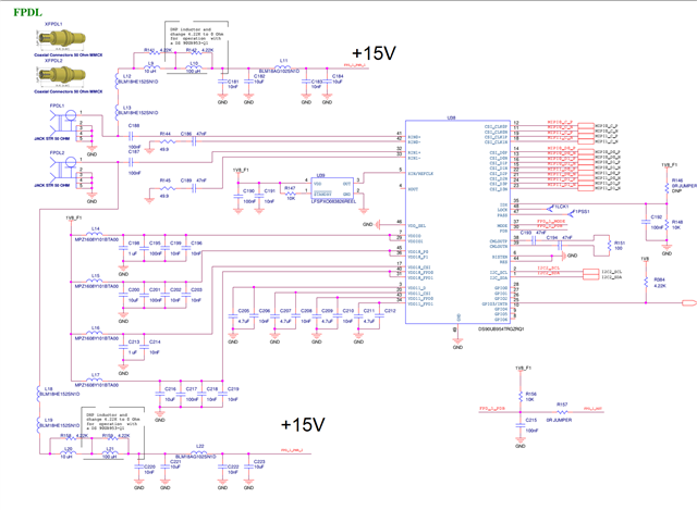
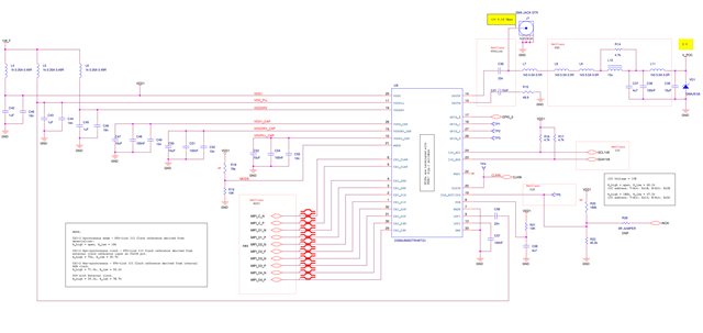
     can you share the schematic for the SER and DES sides?
     

  • Hi, Hamzeh Jaradat.


    Yes, we used the exact same set of components for testing.
    I'm attaching parts of our schematics.

    We currently want to run 4 lanes from the camera.

    But we have another big problem.
    We can't detect the zero channel of the deserializer to which the serializer is connected.

    The channels and the serializers connected to them are completely identical to the camera.

  • Hi Ivan,

    Looking at your schematic, they both look good.

    What I believe is going on here that there are two issues on your system:

    1) a Back-channel issue, due to the fact that in all tests, your SER is reporting BCC CRC errors. This can be due to bad layout, or PoC filter.

    2) For the Forward-channel issue, I think the imager sensor is shooting the data in a higher speed that the SER/DES can tolerate hence we get the buffer error and the CSI errors. Please reach out to the image sensor's vendor and ask them to provide you with initialization script with lower speed. I know your datarate is pretty low, but I think the Imager CSI-TX is setting idle for sometime and shoots the data with higher speed at once. so if they can reduce the max speed you should have no issues.

    We currently want to run 4 lanes from the camera.

    But we have another big problem.
    We can't detect the zero channel of the deserializer to which the serializer is connected.

    The channels and the serializers connected to them are completely identical to the camera.

    Can you please provide more details? What do you mean by you can not detect the zero channel?

  • Hi, Hamzeh Jaradat.
    We reduced the CSI rate from the camera to the serializer on the direct link.
    This hasn't resulted in any improvement yet.
    I'm attaching the log, but it's similar to the previous one.

    [12:51:02.785] 954-:DEVICE_STS              [0x04]=0xDF
    [12:51:02.786] 954-:CSI_CTL                 [0x33]=0x43
    [12:51:02.786] 954-:CSI_CTL2                [0x34]=0x40
    [12:51:02.786] 954-:FWD_CTL1                [0x20]=0x10
    [12:51:02.787] 954-:FWD_CTL2                [0x21]=0x01
    [12:51:02.787] 954-:CSI_PLL_CTL             [0x1F]=0x00
    [12:51:02.787] 954-:PORT_CONFIG             [0x6D]=0x7C
    [12:51:02.787] 954-:PAR_ERR_THOLD_HI        [0x05]=0x01
    [12:51:02.788] 954-:PAR_ERR_THOLD_LO        [0x06]=0x00
    [12:51:02.788] 954-:RX_PORT_STS1            [0x4D]=0x43
    [12:51:02.788] 954-:RX_PORT_STS2            [0x4E]=0x0C
    [12:51:02.788] 954-:RX_PAR_ERR_HI           [0x55]=0x00
    [12:51:02.788] 954-:RX_PAR_ERR_LO           [0x56]=0x00
    [12:51:02.789] 954-:CSI_RX_STS              [0x7A]=0x0C
    [12:51:02.789] 954-:CSI_ERR_COUNTER         [0x7B]=0xFF
    [12:51:02.789] 954-:LINK_ERROR_COUNT        [0xB9]=0x33
    [12:51:02.790] 954-:PORT_DEBUG              [0xD0]=0x00
    [12:51:02.790] 954-:INTERRUPT_STS           [0x24]=0x00
    [12:51:02.790] 954-:CSI_TX_ICR              [0x36]=0x00
    [12:51:02.791] 954-:CSI_STS                 [0x35]=0x01
    [12:51:02.791] 954-:CSI_TX_ISR              [0x37]=0x00
    [12:51:02.791] 954-:PORT_ICR_HI             [0xD8]=0x00
    [12:51:02.792] 954-:PORT_ICR_LO             [0xD9]=0x00
    [12:51:02.792] 954-:PORT_ISR_HI             [0xDA]=0x00
    [12:51:02.792] 954-:PORT_ISR_LO             [0xDB]=0x00
    
    [12:51:02.792] 953-:RESET_CTL               [0x01]=0x00
    [12:51:02.793] 953-:General_CFG             [0x02]=0x73
    [12:51:02.793] 953-:MODE_SEL                [0x03]=0x48
    [12:51:02.793] 953-:CSI_POL_SEL             [0x20]=0x00
    [12:51:02.793] 953-:CSI_LP_POLARITY         [0x21]=0x00
    [12:51:02.794] 953-:CSI_EN_HSRX             [0x22]=0x00
    [12:51:02.794] 953-:CSI_EN_LPRX             [0x23]=0x00
    [12:51:02.794] 953-:CSI_EN_RXTERM           [0x24]=0x00
    [12:51:02.794] 953-:CSI_PKT_HDR_TINIT_CTRL  [0x31]=0x20
    [12:51:02.794] 953-:DEVICE_ID               [0x00]=0x32
    [12:51:02.795] 953-:BC_CTRL                 [0x49]=0x00
    [12:51:02.795] 953-:GENERAL_STATUS          [0x52]=0x65
    [12:51:02.795] 953-:BIST_ERR_CNT            [0x54]=0x00
    [12:51:02.795] 953-:CRC_ERR_CNT1            [0x55]=0x00
    [12:51:02.796] 953-:CRC_ERR_CNT2            [0x56]=0x00
    [12:51:02.796] 953-:CSI_ERR_CNT             [0x5C]=0x00
    [12:51:02.796] 953-:CSI_ERR_STATUS          [0x5D]=0x00
    [12:51:02.796] 953-:CSI_ERR_DLANE01         [0x5E]=0x00
    [12:51:02.796] 953-:CSI_ERR_DLANE23         [0x5F]=0x00
    [12:51:02.797] 953-:CSI_ERR_CLK_LANE        [0x60]=0x00
    

    What other registers should I attach for further understanding?
    We've checked the schematic several more times, and it looks good.


    Can you please provide more details? What do you mean by you can not detect the zero channel?

    We have two DS90UB954 serializers with cameras connected to the DS90UB954 deserializer.
    When the system boots, only the serializer connected to channel 1 initializes.
    The serializer on channel 0 isn't responding, so a BCC connection can't be established with it.
    Both serializers with cameras are working properly.

  • Hi Ivan,

    It will be helpful if you can dump these registers:
    953: 0x02-0x07, 0x10-0x11, 0x32, 0x37, 0x50-0x52, 0x55, 0x56, 0x5B-0x64
    954: 0x02-0x06, 0x1F-0x24, 0x33-0x37, 0x40-0x49, 0x4C-0x58, 0x5B-0x6D, 0x70-0x76, 0x7A-0x7C, 0xD2-0xDB

    We have two DS90UB954 serializers with cameras connected to the DS90UB954 deserializer.
    When the system boots, only the serializer connected to channel 1 initializes.
    The serializer on channel 0 isn't responding, so a BCC connection can't be established with it.
    Both serializers with cameras are working properly.

    If you write the 954 register 0x4C = 0x01, what is the status of reg 0x4D, 0x4E and 0x58?

  • Hi, Hamzeh Jaradat.

    t will be helpful if you can dump these registers:

    Here are the registers

    [00:03:52.736] 954-:GENERAL_CONF            [0x02]=0x1E
    [00:03:52.736] 954-:REVISION_ID             [0x03]=0x20
    [00:03:52.737] 954-:DEVICE_STS              [0x04]=0xDF
    [00:03:52.737] 954-:PAR_ERR_THOLD_HI        [0x05]=0x01
    [00:03:52.737] 954-:PAR_ERR_THOLD_LO        [0x06]=0x00
    [00:03:52.738] 954-:BCC_WATCH_DOG           [0x07]=0xFE
    [00:03:52.739] 954-:CSI_PLL_CTL             [0x1F]=0x00
    [00:03:52.739] 954-:FWD_CTL1                [0x20]=0x10
    [00:03:52.739] 954-:FWD_CTL2                [0x21]=0x01
    [00:03:52.739] 954-:FWD_STS                 [0x22]=0x00
    [00:03:52.740] 954-:INTERRUPT_CTL           [0x23]=0x00
    [00:03:52.740] 954-:INTERRUPT_STS           [0x24]=0x00
    [00:03:52.740] 954-:CSI_CTL                 [0x33]=0x43
    [00:03:52.740] 954-:CSI_CTL2                [0x34]=0x40
    [00:03:52.741] 954-:CSI_STS                 [0x35]=0x01
    [00:03:52.741] 954-:CSI_TX_ICR              [0x36]=0x00
    [00:03:52.741] 954-:CSI_TX_ISR              [0x37]=0x01
    [00:03:52.741] 954-:RES                     [0x40]=0x00
    [00:03:52.741] 954-:SFILTER_CFG             [0x41]=0xA7
    [00:03:52.742] 954-:AEQ_CTL1                [0x42]=0x71
    [00:03:52.742] 954-:AEQ_ERR_THOLD           [0x43]=0x01
    [00:03:52.742] 954-:RES                     [0x44]=0x00
    [00:03:52.742] 954-:RES                     [0x45]=0x00
    [00:03:52.743] 954-:RES                     [0x46]=0x00
    [00:03:52.743] 954-:RES                     [0x47]=0x00
    [00:03:52.743] 954-:RES                     [0x48]=0x00
    [00:03:52.743] 954-:FPD3_PORT_SEL           [0x4C]=0x12
    [00:03:52.744] 954-:RX_PORT_STS1            [0x4D]=0x43
    [00:03:52.744] 954-:RX_PORT_STS2            [0x4E]=0x4D
    [00:03:52.744] 954-:RX_FREQ_HIGH            [0x4F]=0x64
    [00:03:52.744] 954-:RX_FREQ_LOW             [0x50]=0x00
    [00:03:52.745] 954-:SENSOR_STS_0            [0x51]=0x00
    [00:03:52.745] 954-:SENSOR_STS_1            [0x52]=0x00
    [00:03:52.745] 954-:SENSOR_STS_2            [0x53]=0x03
    [00:03:52.745] 954-:SENSOR_STS_3            [0x54]=0x00
    [00:03:52.746] 954-:RX_PAR_ERR_HI           [0x55]=0x00
    [00:03:52.746] 954-:RX_PAR_ERR_LO           [0x56]=0x00
    [00:03:52.746] 954-:BCC_CONFIG              [0x58]=0x5E
    [00:03:52.747] 954-:SER_ID                  [0x5B]=0x32
    [00:03:52.747] 954-:SER_ALIAS               [0x5C]=0x40
    [00:03:52.747] 954-:TARGET_ID0              [0x5D]=0x34
    [00:03:52.747] 954-:TARGET_ID1              [0x5E]=0x00
    [00:03:52.748] 954-:TARGET_ID2              [0x5F]=0x00
    [00:03:52.748] 954-:TARGET_ID3              [0x60]=0x00
    [00:03:52.748] 954-:TARGET_ID4              [0x61]=0x00
    [00:03:52.748] 954-:TARGET_ID5              [0x62]=0x00
    [00:03:52.749] 954-:TARGET_ID6              [0x63]=0x00
    [00:03:52.749] 954-:TARGET_ID7              [0x64]=0x00
    [00:03:52.749] 954-:TARGET_ALIAS0           [0x65]=0x38
    [00:03:52.749] 954-:TARGET_ALIAS1           [0x66]=0x00
    [00:03:52.750] 954-:TARGET_ALIAS2           [0x67]=0x00
    [00:03:52.751] 954-:TARGET_ALIAS3           [0x68]=0x00
    [00:03:52.751] 954-:TARGET_ALIAS4           [0x69]=0x00
    [00:03:52.751] 954-:TARGET_ALIAS5           [0x6A]=0x00
    [00:03:52.752] 954-:TARGET_ALIAS6           [0x6B]=0x00
    [00:03:52.753] 954-:TARGET_ALIAS7           [0x6C]=0x00
    [00:03:52.753] 954-:PORT_CONFIG             [0x6D]=0x7C
    [00:03:52.753] 954-:RAW10_ID                [0x70]=0x6B
    [00:03:52.753] 954-:RAW12_ID                [0x71]=0x6C
    [00:03:52.754] 954-:CSI_VC_MAP              [0x72]=0x55
    [00:03:52.754] 954-:LINE_COUNT_HI           [0x73]=0x04
    [00:03:52.754] 954-:LINE_COUNT_LO           [0x74]=0x3A
    [00:03:52.755] 954-:LINE_LEN_1              [0x75]=0x09
    [00:03:52.755] 954-:LINE_LEN_0              [0x76]=0x60
    [00:03:52.755] 954-:FREQ_DET_CTL            [0x77]=0xC5
    [00:03:52.755] 954-:CSI_RX_STS              [0x7A]=0x0C
    [00:03:52.756] 954-:CSI_ERR_COUNTER         [0x7B]=0xFF
    [00:03:52.756] 954-:PORT_CONFIG_2           [0x7C]=0x20
    [00:03:52.756] 954-:LINK_ERROR_COUNT        [0xB9]=0x33
    [00:03:52.756] 954-:PORT_DEBUG              [0xD0]=0x00
    [00:03:52.757] 954-:AEQ_CTL1                [0xD2]=0x94
    [00:03:52.757] 954-:AEQ_STATUS              [0xD3]=0x02
    [00:03:52.757] 954-:ADAPTIVE EQ BYPASS      [0xD4]=0x60
    [00:03:52.757] 954-:AEQ_MIN_MAX             [0xD5]=0xF2
    [00:03:52.758] 954-:RES                     [0xD6]=0x00
    [00:03:52.758] 954-:RES                     [0xD7]=0x00
    [00:03:52.759] 954-:PORT_ICR_HI             [0xD8]=0x00
    [00:03:52.760] 954-:PORT_ICR_LO             [0xD9]=0x00
    [00:03:52.760] 954-:PORT_ISR_HI             [0xDA]=0x00
    [00:03:52.760] 954-:PORT_ISR_LO             [0xDB]=0x08
    [00:03:52.760] 953-:DEVICE_ID               [0x00]=0x32
    [00:03:52.761] 953-:RESET_CTL               [0x01]=0x00
    [00:03:52.761] 953-:General_CFG             [0x02]=0x73
    [00:03:52.762] 953-:MODE_SEL                [0x03]=0x48
    [00:03:52.762] 953-:BC_MODE_SELECT          [0x04]=0x00
    [00:03:52.762] 953-:PLLCLK_CTRL             [0x05]=0x03
    [00:03:52.763] 953-:CLKOUT_CTRL0            [0x06]=0x41
    [00:03:52.763] 953-:CLKOUT_CTRL1            [0x07]=0x28
    [00:03:52.763] 953-:DVP_CFG                 [0x10]=0x00
    [00:03:52.764] 953-:DVP_DT                  [0x11]=0x00
    [00:03:52.764] 953-:CSI_POL_SEL             [0x20]=0x00
    [00:03:52.764] 953-:CSI_LP_POLARITY         [0x21]=0x00
    [00:03:52.764] 953-:CSI_EN_HSRX             [0x22]=0x00
    [00:03:52.765] 953-:CSI_EN_LPRX             [0x23]=0x00
    [00:03:52.765] 953-:CSI_EN_RXTERM           [0x24]=0x00
    [00:03:52.765] 953-:CSI_PKT_HDR_TINIT_CTRL  [0x31]=0x20
    [00:03:52.766] 953-:BCC_CONFIG              [0x32]=0x88
    [00:03:52.766] 953-:DES_ID                  [0x37]=0x60
    [00:03:52.766] 953-:BC_CTRL                 [0x49]=0x00
    [00:03:52.766] 953-:REV_MASK_ID             [0x50]=0x20
    [00:03:52.767] 953-:DEVICE_STS              [0x51]=0xC0
    [00:03:52.767] 953-:GENERAL_STATUS          [0x52]=0x65
    [00:03:52.767] 953-:BIST_ERR_CNT            [0x54]=0x00
    [00:03:52.767] 953-:CRC_ERR_CNT1            [0x55]=0x00
    [00:03:52.767] 953-:CRC_ERR_CNT2            [0x56]=0x00
    [00:03:52.768] 953-:CSI_ERR_CNT             [0x5C]=0x00
    [00:03:52.768] 953-:CSI_ERR_STATUS          [0x5D]=0x00
    [00:03:52.768] 953-:CSI_ERR_DLANE01         [0x5E]=0x00
    [00:03:52.769] 953-:CSI_ERR_DLANE23         [0x5F]=0x00
    [00:03:52.769] 953-:CSI_ERR_CLK_LANE        [0x60]=0x00
    [00:03:52.769] 953-:CSI_PKT_HDR_VC_ID       [0x61]=0x12
    [00:03:52.769] 953-:PKT_HDR_WC_LSB          [0x62]=0x60
    [00:03:52.770] 953-:PKT_HDR_WC_MSB          [0x63]=0x09
    [00:03:52.770] 953-:CSI_ECC                 [0x64]=0x12


    I read the status of the registers

    0x4C = 0x01

    0x4D = 0x00
    0x4E = 0x02
    0x58 = 0x5E

  • Hi Ivan,

    From the register dump I can see the following:

    This dump is from RX Port1. LOCK and PASS are stable.

    in reg 0x4E= 0x0x4D -- Line length and Line count changed. And CSI errors (length and checksum errors) are reported. Error count is 0xFF.

    The received video has the resolution 0f 1082 x 1920, RAW10 data type.

    AEQ = 2 which indicates a stable good quality link.

    All reported errors are CSI errors. Not a single FPD-Link error. which means the issue is coming from the image sensor or the interface between the SER and the Image sensor.

    From your RX Port0 registers, we can see there is no LOCK or PASS.

  • Hi, Hamzeh Jaradat.

    We found why our first channel wasn't working.
    The DS90UB954 wasn't detecting the serializer on channel one.
    Our DS90UB954 was receiving a signal from a resistive divider on the MODE:37 pin, and the 10K/95K values ​​didn't correspond to any mode.

    The documentation says that the mode is set at startup using the resistive divider.
    Then, using the appropriate registers, you can completely change the mode.
    Our modes are set using registers, but this didn't happen until we removed the incorrect resistors.
    Why weren't the register settings working?

    But this didn't fix the problem with image capture on four CSI lines, which wasn't working for us. Here's a quick rundown of what's working.
    1. Image capture from the sensor works on 2 lines.
    2. The DS90UB954 deserializer test pattern works and is displayed on the display on 4 lines.
    3. The DS90UB953 serializer test pattern works and is displayed on the display on 4 lines.

    Based on the serializer test pattern, we can say that the hardware is working fine.
    We suspect there are issues between the image sensor and the serializer.

    We've checked the PCB design several times and also checked all the drivers.
    There are no issues.

    We want to understand the synchronization principles throughout the entire image capture channel.

    Our imx412 camera sensor currently operates at 24 MHz.
    The DS90UB954 deserializer operates at a synchronization frequency of 25 MHz. The DS90UB954 -> DS90UB953 channel operates in synchronous mode.

    We want to receive the deserializer clock frequency via the reverse channel and feed it to the image sensor from pin 19 of the DS90UB953.
    It's not yet clear whether we can get 24 MHz from pin 19 of the DS90UB953.

    How feasible is this solution?

  • Hello Ivan,

    The documentation says that the mode is set at startup using the resistive divider.
    Then, using the appropriate registers, you can completely change the mode.
    Our modes are set using registers, but this didn't happen until we removed the incorrect resistors.
    Why weren't the register settings working?

    It is probably because the MODE pin is strapped into an invalid mode. The device must be in a valid mode then can be put into another mode using registers.

    We want to receive the deserializer clock frequency via the reverse channel and feed it to the image sensor from pin 19 of the DS90UB953.
    It's not yet clear whether we can get 24 MHz from pin 19 of the DS90UB953.

    How feasible is this solution?

    There are two settings which you can use on the UB953:
    reg 0x06 = 0x43, reg 0x07 = 0x7D will give you exactly 24MHz on CLKOUT pin. But the jitter will be around 1ns.

    If you want much lower jitter (~100pS) then you should use reg 0x06 = 0x41, reg 0x07 = 0x2A, But you will not be getting exact 24MHz, instead the generated frequency will be 23.81MHz.