This thread has been locked.

If you have a related question, please click the "Ask a related question" button in the top right corner. The newly created question will be automatically linked to this question.

SN65LVDS049: 50 ohms in series with current source?

Part Number: SN65LVDS049

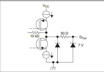
Hello, I have a question regarding the SN65LVDS049 output driver block diagram (figure 10).  What is the purpose of the 50 ohms in series with the output if the output is a current source?  Surely 50 ohms is negligible compared to the current source output impedance.


image.png


  • Hello Mark,

    This is an integrated series termination resistor that is used to ensure the impedance of the driver matches the impedance of the transmission media and end or parallel termination resistance at the receiver end of the channel.

    As the signal propagated down the channel, a portion of the signal will be reflected when there is a change in the characteristic impedance.  Simplifying the channel elements down to a driver, transmission media (PCB traces, coax cables, or twisted pair wires, etc.), and a receiver.  Ideally the impedance of all elements are equal and there will not be any reflected energy.  

    However, the receiver is typically Hi-Z so a parallel termination is placed close to the pins of the receiver.  And the Driver is usually Low Impedance, so adding a series resistance in or near the driver will help match the impedance to the transmission media as well as dampen any energy that is reflected back.

    Regards,

    Jonathan

  • I would understand the impedance matching / reflections explanation if it was a low impedance output ( voltage source driver).  The datasheet shows a current source in series with the output transistors - as expected for an LVDS driver.   So why put 50 ohms in series with an ouptput that is already high impedance?

  • The series resistors are used to match the driver impedance to the transmission media and reduce reflections.  Each driver pin is 50 ohms and together that makes a differential 100 ohms.  This means the driver, transmission media, and receiver with parallel termination resistor will all match and minimize reflections.  The datasheet parameters already account for the presence of these resistors.

  • How is each output 50 ohms?  The 50 ohms is shown in series with a current source ( infinite, or at least >>50 ohms output resisntance).  50 + infinity = infinity , not 50.

  • The driver impedance is not infinite when it is actively driving.  This would be the state when the the driver is disabled or not active.  It wouldn't be possible to source the required current across a driver that has infinite impedance. 

    Typically an active driver has low impedance, or a lot resistance across the driver transistors.  To reduce reflections it is common to add a series resistor at the output of the driver such that the total equivalent impedance of the driver and this series resistor matches the characteristic impedance of the transmission line.

    Zdriver + Zresistor = Zline

    The equivalent Output Diagram shows this series resistor has been added internally such that the impedance of the driver is essentially 50 ohms to match the PCB trace and transmission line impedance.  The datasheet states this device should be used with a transmission line impedance of 100 ohms.  Because uses an H-Bridge driver, there is a transistor connecting one of the DO pins High, and another transistor connecting the other Low at all times.  Each DO pin will therefore have a 50 ohm series resistor between the pin and the current source.

    Essentially the purpose of this output diagram is showing that the driver has been optimized for use with a 100 ohm transmission line characteristic impedance.