This thread has been locked.

If you have a related question, please click the "Ask a related question" button in the top right corner. The newly created question will be automatically linked to this question.

DP83869HM: DP83869HM: Review schematic designed for SGMII mode (1000 Mbps)

Part Number: DP83869HM
Other Parts Discussed in Thread: DP83869, DP83869EVM

Hi,

We are using the DP83869HM Ethernet PHY in SGMII mode (1000 Mbps) with a 2-supply configuration. The SGMII interface is connected to the MPU, and the MDI signals are connected to an RJ-45 connector.

Kindly review the attached schematic diagram and clarify the following questions:

eth_phy (1).png

  1. Is it require to connect 3.3 V supply, whenever the voltage level of IO pins is 1.8V?
  2. Are the EMI filters used on the 1.8 V, 2.5 V, and 1.1 V supply rails sufficient for noise suppression?
  3.  Are the pull-up resistors connected to RX_D[3..0], JTAG_TMS, JTAG_TDI, and JTAG_CLK correctly configured to set SGMII to Copper mode?
  4. We are using the PHY with VDDIO = 1.8 V. Are the current connections correct for this configuration?
  5. The clock frequency for SGMII mode is 625 MHz. What should be the crystal oscillator frequency used for SGMII operation?
  6. Is a 3-supply configuration required, or is a 2-supply configuration sufficient? If a 3-supply configuration is required, under what conditions would it be necessary?
  7. Why and when are coupling capacitors required between the MPU and the Ethernet PHY on the SGMII lines?

Thank You
Rajeev Kumar

  • Hi Rajeev,

    1. No, you do not need a 3.3V supply if using 1.8V VDDIO. The only required power rails for DP83869 are 2.5V, 1.1V, and the VDDIO.

    2. Your decoupling scheme looks good on the supply rails.

    3. Yes, RX_D2 and RX_D3 are pulled high while JTAG_TDO is pulled low. This would configure the PHY to SGMII to Copper

    4. The VDDIO voltage will be detected by the PHY. You've got the I/O pins pulled up to the VDDIO rail as well which is correct, however I recommend leaving the pullup on MDC (R64) depopulated. MDC does not require a pullup.

    5. The crystal oscillator should be 25MHz in all operating modes.

    6. 2-supply configuration is sufficient. 3-supply configuration can reduce the overall power draw of the PHY but will be functionally equivalent to two supply operation.

    7. AC coupling is always a requirement between the PHY and MPU on the SGMII lines. This is to isolate the common mode voltage on either side.

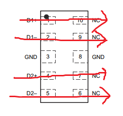
    We have a DP83869 schematic checklist that is a good tool to use when designing in this PHY. I recommend taking a look at the 'pin wise checklist' tab for in-depth descriptions of each pin. The high speed connections in your image look ok, however I'd recommend using a pass-through ESD diode such as what is used on our DP83869EVM:

    Best,

    Shane

  • Hi Shane,

    Thanks for your reply. Can you please give us the clearity on ESD protection diode? We already used TVS diode on MDI signals.

    Regards,
    Rajeev Kumar

  • Hi Rajeev,

    Its better to use an ESD diode that passes the MDI traces straight through, rather than using an ESD diode that hangs off the side of the MDI trace. In your schematic, the ESD diodes appear to connect at one point in the MDI trace rather than passing the physical trace through the diode itself.

    For example the ESD diodes used on DP83869EVM pass the MDI traces through the diode, thus minimizing stubs on the MDI trace. A stub is a section of the trace that 'hangs off' the main signal path. These stubs can add reflections to the signal and reduce signal quality. If possible, I'd recommend switching to a diode that can pass signals through, such as TPD4E05U06DQAR

    Best,

    Shane