TDP142-Q1: TDP142-Q1 about I2C Setting issue

Part Number: TDP142-Q1

Hi, Support Team

We saw the datasheet of TDP142-Q1 about PIN13 and Pin14 have two question:

Q1: "pull up this pin to the VCC I2C supply of the I2C controller "  should I external pull resistor with 1.8V?  if yes, any suggest resistor value?

q1.png

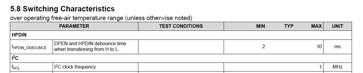
Q2: About I2C default speed is 1MHz?

 Q2.png

if any suggestion, Please advise me.

Thanks,

Best regards,

Lawrence


  • Hi Lawrence, 

    Typically, I2C runs in 100 to 400kHz and that is also the case for this device. We can support up to 1MHz. 

    For I2C pullup, please use 4.7k pullup. 

    Best,
    J


  • Hi J,

    Thank you for your reply. Let me confirm the scenario as below:

    i2c_en ==> f = i2c enabled at 1.8V when rsvd11 = "0" and rsvd10 = "0". Otherwise, it is in GPIO mode (i2c disabled).

    So, to enable I2C at 1.8V, the following three conditions are required:

    (1) i2c_en = f (float, leave pin open)

    (2) rsvd11 = "0"

    (3) rsvd10 = "0"

    If yes, do pin 13 (test/scl) and pin 14 (test/sda) need a 4.7k pull-up resistor?

    Note:

    in Fast mode(400kHz) pull up resistor range is 620ohm to 2.2k, typical is 1.5k?

    in Fsst mode+(1MHz) pull up resistor range is 1.5k to 2k, typical is 4.7k?

    if any suggestion, Please advise me.

    Thanks,

    Best regards,

    Lawrence

  • Hi Lawrence, 


    So, to enable I2C at 1.8V, the following three conditions are required:

    (1) i2c_en = f (float, leave pin open)

    (2) rsvd11 = "0"

    (3) rsvd10 = "0"

    If yes, do pin 13 (test/scl) and pin 14 (test/sda) need a 4.7k pull-up resistor?

    Yes, this is correct. I advise to keep 4.7k for both modes of I2C.

    Best,

    J