TCAN284XEVM: TCAN284xEVM - SPI Write Issue on TCAN284xEVM

Part Number: TCAN284XEVM
Other Parts Discussed in Thread: MSPM0G3519,

I am working with the TCAN284xEVM (Slave) and MSPM0G3519 (Master). I am trying to establish the SPI interface between the slave and the master. I am able to read the DEVICE ID register (all 7 values).

image.png

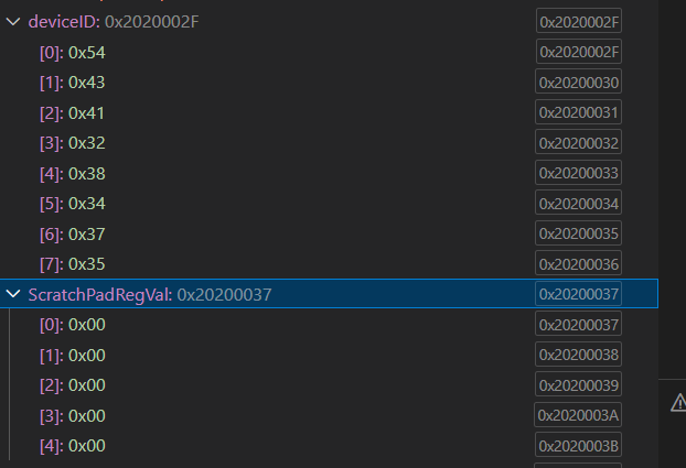
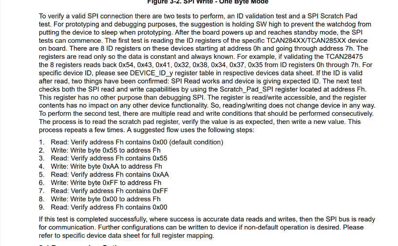
To validate the SPI write operation, I used the Scratch_Pad_SPI register and followed the same steps mentioned below.

image.png

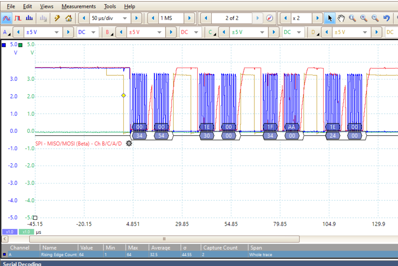
However, after performing the write operation, when I read the Scratch_Pad_SPI register, it still returns 0x00. This suggests that the SPI write is not taking effect. I verified both the SPI read and SPI write frames using a Picoscope, and all frames appear to be correct.

1st FRAME: SPI READ  ADDRESS : 0x00 and EXPECTED Value : 0x54.

2nd FRAME : SPI READ ADDRESS: 0x0F and EXPECTED Value: 0x00.

3rd FRAME: SPI WRITE ADDRESS: 0x0F and DATA :0xAA.

4th FRAME: SPI READ ADDRESS: 0x0F and EXPECTED Value: 0xAA. (But I am getting 0x00, means SPI WRITE FAILED).

image.png

Additionally, I observed that on the EVM, the D22 LED is continuously ON, which corresponds to the nINT indicator pin.

Could you please help me identify and resolve this SPI write issue.

Regards,

SaKhan

  • Hi SaKhan,

    Thanks for reaching out. We will review and get back to you next week. 

    Regards,

    Matt

  • Hi SaKhan,

    The D22 LED illuminates when there is an interrupt on the device. It will stop illuminating when you clear the interrupts. 

    Can you separate and label your SPI waveforms so I can see how you are sending them? Also, can you read the REV_ID from register 08h?

    Regards,

    Matt 

  • Hi Matt Smith,

    SPI waveform:


    Also, Please find the below REV data and INT data,

    Please let me know if any details required from my end.

    Regards,

    Sakhan

  • Hi Sakhan,

    If the green curve is MISO (connected to the SDO pin of the SBC), then the waveform shows 0V continuously, so I'm not quite sure how you are able to read any register data. Can you elaborate on this?

    Also, if the red curve is MOSI (connected to the SDI pin of the SBC), it looks like there is a 4V spike in between the address byte and data byte of each transaction. That could be causing issues too. Is the MCU programmed to pull this pin high in between bytes like this? Also, what is the SCK frequency?

    Lastly, have you made any register changes, or are the only SPI transactions reading/writing the REV_ID and SCRATCH_PAD registers as you described in your original post? If you made any configuration changes from the default values, can you please list the changes you made?

    Regards,

    Matt

  • Hi Matt Smith,

    If the green curve is MISO (connected to the SDO pin of the SBC), then the waveform shows 0V continuously, so I'm not quite sure how you are able to read any register data. Can you elaborate on this?

    Yes, that is correct. However, I was able to obtain the global interrupt data (0x34) even though the SDO line was at 0 V, as shown in the write frame screenshot above. Please refer to the another write frame below for further details.

    Also, if the red curve is MOSI (connected to the SDI pin of the SBC), it looks like there is a 4V spike in between the address byte and data byte of each transaction. That could be causing issues too. Is the MCU programmed to pull this pin high in between bytes like this? Also, what is the SCK frequency?

    No. The MCU is configured in SPI 3-wire mode with manual CS pin toggling. It is not intentionally programmed to pull the MOSI pin high between bytes.

    Lastly, have you made any register changes, or are the only SPI transactions reading/writing the REV_ID and SCRATCH_PAD registers as you described in your original post? If you made any configuration changes from the default values, can you please list the changes you made?

    No, we did not change any default register values. As described in the TCAN284xEVM User Guide, we only performed the SPI tests (ID validation test and SPI Scratch Pad test).

    The D22 LED illuminates when there is an interrupt on the device. It will stop illuminating when you clear the interrupts. 

    To clear nINT, I read the interrupt register to clear the interrupts, but the D22 LED remains continuously ON. Will this affect the SPI write operation.

    1. How can I clear the D22 LED (nINT)?

    2. How can I verify whether our EVM is working properly or not?

    3.Could you please check and let me know if there are any issues with my SPI frames?

    4. Is any hardware modification required on the EVM?

    5. Why is the write frame being discarded by the EVM? I am using the same SPI transmit function.

    Regards,

    SaKhan

  • Hi SaKhan,

    I just noticed something about your MCU connection to the EVM. From the image you shared in your original post, it looks like you don't have the CLK pin connected to a jumper on the J29 header and instead you have GFO connected to something. If that's the case, you aren't connecting the correct SPI pins from the MCU to the EVM. The waveforms you sent indicate a connection issue because the MOSI line should be what the MCU is sending to the SDI pin of the SBC. However, if that's the case, you are just sending 0x34 0x00 which is just the command to read the SPI_CONFIG1 register. 

    Once you fix the jumper connections to J29, this should solve the issue. (Clock -> CLK; MOSI -> SDI; MISO -> SDO; Chip Select  -> nCS)

    Regards,

    Matt

  • Hi Matt,

    I verified the SPI connections between my MCU and the TCAN284xEVM board. The pins are connected as follows: Clock → CLK, MOSI → SDI, MISO → SDO, and Chip Select → nCS.

    I am able to read all the TCAN284xEVM register values successfully. However, I noticed that some register values are different from the default values mentioned in the datasheet. I read all the register values immediately after powering up the EVM and did not modify any of the default register values. Could you please confirm whether this behavior is expected?

    Register Reset Value Present Value
    DEVICE_ID Fixed 54 43 41 32 38 34 37 35
    REV_ID Device specific 0x21
    SPI_CONFIG 0x00 0xFF
    CRC_CNTL 0x00 0x00
    CRC_POLY_SET 0x00 0x00
    SBC_CONFIG 0x06 0xD7
    VREG_CONFIG1 0x00 0xFF
    SBC_CONFIG1 0x00 0xB9
    SCRATCH_PAD 0x00 0x00
    CAN_CNTRL_1 0x00 0x04
    WAKE_PIN_CONFIG1 0x00 0x1F
    WAKE_PIN_CONFIG2 0x00 0x63
    WD_CONFIG_1 0x00 0xFF
    WD_CONFIG_2 0x00 0xE1
    WD_INPUT_TRIG 0x00 0x00
    WD_RST_PULSE 0x00 0xF0
    FSM_CONFIG 0x00 0x00
    FSM_CNTR 0x00 0x00
    DEVICE_CONFIG0 0x00 0xF0
    DEVICE_CONFIG1 0x00 0x91
    DEVICE_CONFIG2 0x00 0x01
    SWE_TIMER 0x28 0xE8
    LIN_CNTL 0x00 0x00
    HSS_CNTL 0x00 0x00
    PWM1/2 registers 0x00 0x00
    TIMER1/2 0x00 0x00
    RSRT_CNTR 0x00 0x00
    RST_CNTL 0x00 0x00
    INT_GLOBAL 0x00 0x34
    INT_1 0x00 0x00
    INT_2 0x00 0x50
    INT_3 0x00 0x81
    INT_CANBUS_1 0x00 0x00
    INT_7 0x00 0x00
    INT_EN_1 0x00 0xFF
    INT_EN_2 0x00 0x7E
    INT_EN_3 0x00 0xFE
    INT_EN_CANBUS 0x00 0xBF
    INT_4 0x00 0x02
    INT_6 0x00 0x00
    INT_EN_4 0x00 0xDF
    INT_EN_6 0x00 0xFF
    INT_EN_7 0x00 0xFF

    Additionally, when I try to write a value to the Scratch Pad register (0x0F), the write operation does not work and the value is not updated.

    I have a few questions regarding the TCAN284xEVM operation:

    1. How can I clear the D22 LED (nINT)?

    2. How can I verify whether our EVM is working properly or not?

    3. Could you please check and let me know if there are any issues with my SPI write frames?

    4. Is any hardware modification required on the EVM?

    5. Why is the write frame being discarded by the EVM? I am using the same SPI transmit function which used for SPI read.

    6. How to debug this SPI write frames. I verified with the EVM datasheet, the frames are proper.

    I would appreciate your guidance on the above questions.

    Regards,

    SaKhan

  • Hi SaKahn,

    Thank you for sharing the interrupt data and confirming the SPI pin connections. After going through the interrupt data, there are two flagged bits that are particularly concerning to me: the CRC_EEPROM and SPIERR bits in INT_3. A SPIERR interrupt indicates improper SPI communication to the device. The CRC_EEPROM interrupt indicates an issue with the EEPROM which can affect device performance and functionality. Unfortunately, that means the device needs to be replaced. You can request free samples on the TCAN2847-Q1 product page

    Did you try to program the EEPROM at all with this device before testing the scratch pad? If you are configuring the EEPROM with improper SPI communication, that could corrupt it. Also, can you send a clear close-up picture of the device's topside marking via a direct message? It's hard to read from your previous pictures. 

    Here are my answers to your questions:

    1. D22 will illuminate when there is an interrupt and nINT is pulled low by the device. To pull nINT high, all the interrupts must be cleared. 

    2. Make sure you are properly powering the device and check the output of Vcc1 and Vcc2. If you are not servicing the watchdog, the SW pin need to be pulled high via a shunt on J23, otherwise the device will go to sleep mode (this will cause an interrupt until you disable watchdog). After that, if you are trying to test SPI functionality, I would say what you are trying to do with the scratch pad register is a good way to test functionality. If something is wrong, the interrupt registers should tell you. 

    3. The latest SPI frames you sent looks fine other than the middle portion of the MOSI signal slowly rising. There are a internal configurable pullup and pulldown resistors on this pin that can changed via the SPI_CONFIG register. Depending on what your MCU SPI pins are doing, the pulldown might need to be changed to a pullup. However, since you are reading 0xFF from that register, that tells me its corrupted anyway since bits 7-4 are read only and supposed to be 0.

    4. It depends on how you want to use the board since there are many things that can be enabled/disabled via shunts such as the SiC network for the CAN bus. However, for basic SPI commands, you should make sure you are applying power the VSUP (put 12V on J3 or J4), make sure the SW pin is active (as mentioned in answer #2), and if you are using an off-board MCU, make sure the switches in S2 connected to the on-board MCU are off.

    5. Most likely due to the EEPROM. 

    6. Make sure you are checking the device datasheet as well. The EVM user guide does not give all the details about the device. 

    Regards,

    Matt

  • Hi Matt,

    I have shared the EVM image via direct message. Kindly check and let me know.

    No, we have not modified any EEPROM registers, as the SPI write operation is not working.

    Regards,

    SaKhan

  • Hi SaKhan,

    It doesn't look like the DM went through. I think we might need to be friends on E2E first. I just sent you a friend request. Accept it and see if you can send it again. 

    Regards,

    Matt

  • Hi Matt,

    1. According to SBC_CONFIG (0xD7), the SBC is in standby mode. Are there any hardware wake pins available to transition from standby mode to normal mode?

    2. As SPI communication is not functioning, the registers remain at their default or EEPROM-defined values from the EVM. By default, which transceiver is active - LIN or CAN? Our work is currently on hold due to the SPI write issue, and I would like to test the transceiver in the meantime.

    3. Is it possible to modify the TCAN register values without using SPI?

    Regards,

    SaKhan

  • Hi SaKhan,

    1.) Transitioning from Standby to Normal mode requires a SPI command. 

    2.) As mentioned earlier, your EEPROM is corrupted which means the device you currently have will not work properly. You will need to replace it. Please send me a DM with a picture of the top-side marking of the device you currently have. We can continue this conversation via DM. 

    3.) No. SPI communication is needed to use this device. 

    Regards,

    Matt

  • Hi Matt,

    For further verification, I replaced the TCAN IC on the EVM. However, the read operation did not work.

    With the old IC, the read operation worked fine.

    Regards,

    SaKhan

  • Hi SaKhan,

    Matt is out of office today, but he will get you a response soon. Thanks for your patience.

    -Ethan

  • Hi SaKhan, 

    Can you describe the steps you took to experience the read issue once you solder the device on? Did you check the continuity to make sure no pins are being shorted and that they all have proper contact with their solder pads? Are you sending the correct SPI waveforms this time? 

    Regards,

    Matt