This thread has been locked.

If you have a related question, please click the "Ask a related question" button in the top right corner. The newly created question will be automatically linked to this question.

TMDS1204: HDMI 2.1 FRL Mode Pin Strapping Configuration

Part Number: TMDS1204

Hi Team,

Could you please provide the pin strapping configuration required to enable FRL mode in HDMI 2.1?

Specifically, I would like to know:

  • The required strap pin settings for FRL TX mode

  • The required strap pin settings for FRL RX mode

  • Any additional configuration needed to enable FRL instead of TMDS during initialization.

Your guidance would be very helpful for debugging our HDMI 2.1 setup.

Regards,
Santhiya

  • Santhiya

    Please see this app note, https://www.ti.com/lit/an/slla612/slla612.pdf, for TMDS1204 generic configuration. The TMDS1204 does not have a specific configuration for FRL TX or FRL RX mode. In pin strap mode, the TMDS1204 uses DDC snooping to automatically configure itself as TMDS or FRL re-driver.

    Thanks

    David

  • Hi David,

    Could you please confirm the configuration of the MODE pin for both TX and RX when operating in FRL mode?

    Regards,
    Santhiya

  • Santhiya

    Mode pin is associated with the TMDS1204 functional mode configuration as shown below.

    Thanks
    David

  • Hi David,

    In my case, the data is coming out of the FPGA and the stream is up, but nothing is being displayed on the monitor. Could you please advise how we can verify whether the data is reaching the retimer and the HDMI OUT connector?

    Regards,
    Santhiya

  • Santhiya

    Are you not able to see display with any resolution or a particular resolution?

    Can you please share your schematic for review? If you probe the TMDS1204 output, are you able to see valid HDMI signal and does the signal pass the HDMI electrical compliance testing?

    Thanks

    David

  • Hi David,
    here i attached the pin strapping settings of HDMI OUT

    Regards,
    Santhiya

  • Santhiya

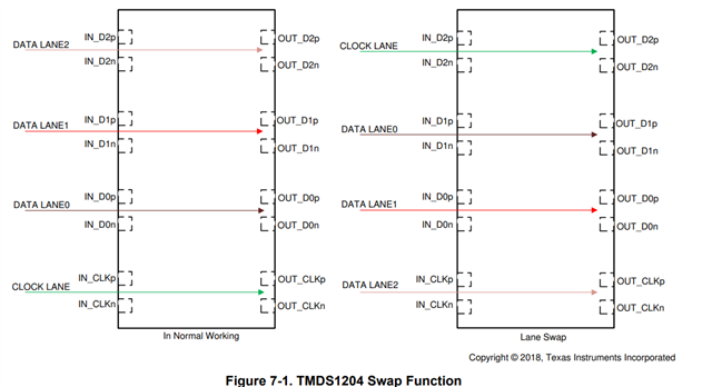
    You have CFG1 pulled high which is the case if the input/output lane order is swapped, is this how you implemented in your design?

    All other strapping pins look ok. Do you only have issue with FRL or also have issue with TMDS as well? 

    Thanks

    David

  • Hi David,

    CFG1 is pulled low; that  change's we made. In our design there is no lane swap 

    In TMDS mode, it is working fine, but in FRL mode the data is not displayed on the monitor.

    Do you have any reference design or pin-strapping settings for FRL mode?

    Regards,
    Santhiya

  • Santhiya

    There is no strapping setting specific for the FRL mode. Is there a way you can capture the DDC log file? I want to make sure the source is correctly communicating the FRL mode to the sink.

    Are you using the TMDS1204 fan out buffer? In some applications the HDMI clock and data must be on separate paths. The TMDS1204 implements a fan-out buffer feature to support such applications. When the fan-out buffer feature is enabled, the TMDS1204 will output the HDMI clock on RCLKOUTp/n when operating in HDMI 1.4 or HDMI 2.0. The OUT_CLKp/n will be disabled. When operating in HDMI 2.1 FRL mode, the TMDS1204 will output FRL data3 on OUT_CLKp/n. RCLKOUTp/n will be disabled. The feature is enabled in pin-strap mode when MODE pin = "R" or it can be enable through FANOUT_EN register when TMDS1204 is configured for I2C mode.

    Thanks

    David