This thread has been locked.

If you have a related question, please click the "Ask a related question" button in the top right corner. The newly created question will be automatically linked to this question.

TVS for AM26LV31E/32E

Other Parts Discussed in Thread: AM26LV32E, AM26LV31E

Hello,

I have to protect 7 differential lines (4 lines in one direction and 3 in the other direction) against transients; I use AM26LV31E and AM26LV32E as drivers and receivers on both sides of a 100 m cable. The maximum frequency is about 1 MHz.

I have very little space on one end, and little space on the other end is always fine.

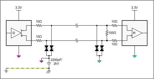
Now I have to find some suitable protections. As AM26LV31E has an absolute maximum voltage of 6 V, I think to use PESD5V0S1BLD from NXP to protect output lines (5 V VRWM, 6 V VBR, 130 W, SOD882D package), while I am thinking about using CDNBS08-T12C (12 V VRWM, 13.3 V VBR, 500 W, SOIC8 package) in order to protect the input lines connected to AM26LV31E.

My question is: as this last package is too big, do you think I could use couples of unidirectional TVSs with reduced power rating? Or is there something else to consider? Is 130 W enough for such a protection?

Do you have any more suggestion, keeping in mind the "very little space" issue?

Thanks in advance,

Stefano

  • Stefano,

    The AM26LV31E would be better served with a unidirectional TVS, otherwise the choice looks good. It should be OK to reduce the 32E TVS rating to save space. Adding an input series resistors to the 32E inputs would more than make up for the reduced TVS capacity.

    Regards,
    Ron Michallick


  • Hi Ron, thanks for your answer.

    Why is AM26LV31E better served with a unidirectional TVS?

    Meanwhile I found these TVSs: CDSOD323-Txx(C) from Bourns. They have a peak pulse power rating of 350 W, and by using single devices (one for each dfferential line, 14 total) the overall area is reduced when compared to PESD5V0S1BLD + CDNBS08-T12C.

    I think they could be a better solution, as I don't have to reduce power rating... I could use the unidirectional 5 V version (CDSOD323-T05) for 31E and bidirectional 12 V version (CDSOD323-T12C) for 32E. As I have little space, do you think I should always provide space for series resistors on 32E, or is the higher power rating of these devices enough?

    Thanks again,

    Stefano 

  • Stefano,

    whenever the clamping voltage of an external TVS exceeds the standoff-votage of the inner driver or receiver, there will be compensation currents flowing into the device. This typically happens when the inner SCRs (silicon controlled rectifiers or ESD structures ignite). One reason for series resistors is to  limit the currents through these, inner protection structures. A second reason is, that when the inner structures conduct, the current through the series resistors causes a voltage drop which together with the voltage drop of the inner ESD structure must be higher than the TVS breakdown voltage to keep the TVS turned on.

    Regards,

    Thomas

  • Thomas,

    if I understand it correctly, you are suggesting to put a resistor in series between each AM26LV32E input and its own external (parallel) TVS. But how can I dimension this resistor?

    I mean, according to the "second reason" I would have to choose a resistor value such that Vclamp_innerESD + RI > VbreakdownTVS. I know the minimum breakdown for my TVS is 13.3 V, but I don't know anything about the current and the clamp voltage of the inner ESD structure... is there a way I can estimate them? And, obviously, the resistor's power rating should assure it can sustain the peak current it has to dissipate...

    Regards,

    Stefano 

  • Stefano,

    yes you are absolutely correct. You would have to know all of this IF THE INNER STRUCTURE IS GETTING USED or IS IGNITED.

    However, a good protection design assures that the inner structure never gets used. If you are fully RS422 compatible you need to include the +/- 7V common-mode to your input voltage. The maximum combined input specified in RS422 is 10V at which the receiver still has to work. Now this is a requirement for the semiconductor manufacturers, not for you as the end customer. You yourself need to know the maximum possible ground potential difference (GPD) between your driver and receivers. Then you add to this the driver output common-mode. On top of this you would add your maximum Vod/2 of the driver. This total would be your maximum positive line voltage, which should not exceed 10V (as stated above). Now if your driver and receivers have a common ground or little GPD then of course your total line voltage is lower.

    The breakdown voltage of your TVS must be above your maximum expected line voltage to allow for proper data transmission across this voltage range. Then if the line voltage is exceeded your TVS kicks in. Now the clamp voltage of this TVS can be higher than the max 14V of the inputs. And shortly above the 14V the inner ESD cells conduct. These SCRs or mini-thyristors often have a small fall-back current once they latch. I personally suggest trying some 100 ohms to 1k ohms input resistors for protection (after your TVS) to limit the current down to very low values and avoid latch-up of the inner SCRs.

    For the driver on the other side you have a similar procedure but your resistor values should be in the 5 to 10 ohms range for a low-impedance driver output. These resistors whether at the driver or receiver, should have high current / voltage pulse robustness. Typically MELF resistors from Vishay-Beyschlag or often High-voltage resistors are used due to their rectangular design. They usually stay on the PCB while MELF resistor in their cylindrical shape often role of the board. (just a minor issue to think off).

    That's all I know. But I'm an RS-485 person try to protect half-duplex transceivers. So I'm always tied to low-impedance 10-ohms resistors.

    Anyway, I hope this helps a bit.

    regards, Thomas


  • Thomas,

    MELF resistors are quite big for my application, as my slave board has to be as small as possible (something like 2x3 cm...), and putting 8 MELF (even micro-MELF) resistors could be an issue.

    So I looked around, and found these resistors from Vishay: CRCW0402100RFKEDHP. They are 100 ohm, 1%, 100 ppm, 50V, 125 mW, 0402 package, rated "high pulse". And they are also quite cheap, which is surely a good add-on.

    Some doubts remain about voltage and power ratings... do you think they're enough? I kept in mind the "small fall-back current" you mentioned... If that "small current" is not small enough, I could use Panasonic ERJ-P03F1000V (100 ohm, 1%, 200 ppm, 150 V, 200 mW, 0603 package), which are 0603 (somewhat bigger, but not that bigger).

    And, as I have AM26LV31E and 32E on both ends of a 100 meters cable (the master side is also isolated), do you think I should put series resistors in driver's outputs and receiver's inputs on both sides?

    Thanks again,

    Stefano

  • Thomas,

    I forgot I have another question for you: where should I put the termination resistor with respect to these input resistors? 

    Thanks again,

    Stefano 

  • Stefano,

    your Panasonic resistors look like a very good choice. Instead of 100 W use 10 W resistors. I'm also attaching a list of Pulse-load resistors from Vishay (just in case). I 'd say the 50V standoff should do.

    Now the ISOLATED driver came with a surprise to me. So I drew up a grounding scheme for one channel only (which of course applies in both directions). The different ground colours indicate different circuit grounds to which the TVS diodes are connected. I assume that your receiver's circuit ground is directly (DC) connected to chassis and Earth ground. Because your isolated driver's ground is not connected directly to ground you MUST have some an AC path for the fast transients to escape to Earth ground.

    If not, then your TVS might conduct and divert transient currents to the local circuit ground where they are stuck and still cause suffient voltage and electric field strength than can arc to adjacent components and damaging them. (Well this is the theory).  I have not experienced it though, and if possible I don't like to experience never.

    For high voltage capacitors providing this AC path look at the VOVACAP site. They provide a good arsenal portfolio.

    I hope this gets your design going.                           Good luck - Thomas

    Pulse Load Chip Resistor.pdf
  • Stefano,

    one more important advise I forgot to emphasize. Place your TVS diodes as close to the bus entrance or connector as possible. The same holds true for the HV-Cap. Transients should never make it into your board but should be diverted to Earth as early as possible.

    So long - Thomas

  • Thomas,

    as my application needs to carry an SPI interface to a distance of 100 meters, I followed your article on AAJ, 4Q 2011. There you suggest to connect both drivers and receivers to earth ground through a 4.7nF 2 kV cap, so I thought to put such a capacitor in both sides... but now I have some doubts and I'm a little confused... where do you suggest to put the high voltage cap? Both on master (4 isolated TX, 3 isolated RX for me) and on slave (3 TX, 4 RX, not isolated), or only on one side?

    Thanks again for your greatly appreciated help.

    Stefano

    Edit: by the way, I guess you suggested 10 OHM resistors, not 10 WATT... right? ;) 

  • Stefano,

    keep what you have. I did not know that you were designing an extended SPI interface. From your previous email I understood that you had only the driver isolated. This was a pure misunderstanding from my side. So nothing to worry about.

    regards, Thomas