This thread has been locked.

If you have a related question, please click the "Ask a related question" button in the top right corner. The newly created question will be automatically linked to this question.

DS26LV32AQML: Unused channel treatment

Part Number: DS26LV32AQML

Hi,
Customer is using only RO1 but there is different operation by RO2 control.

Issue: At U50, there is no output in RO with RI-, RI+input.

  1. RO2(#6), RI2+(#7) connected to GND -> RO1 normal output
  2. RO2(#6) pull down(10k), RI2+(#7) to GND -> RO1 no output
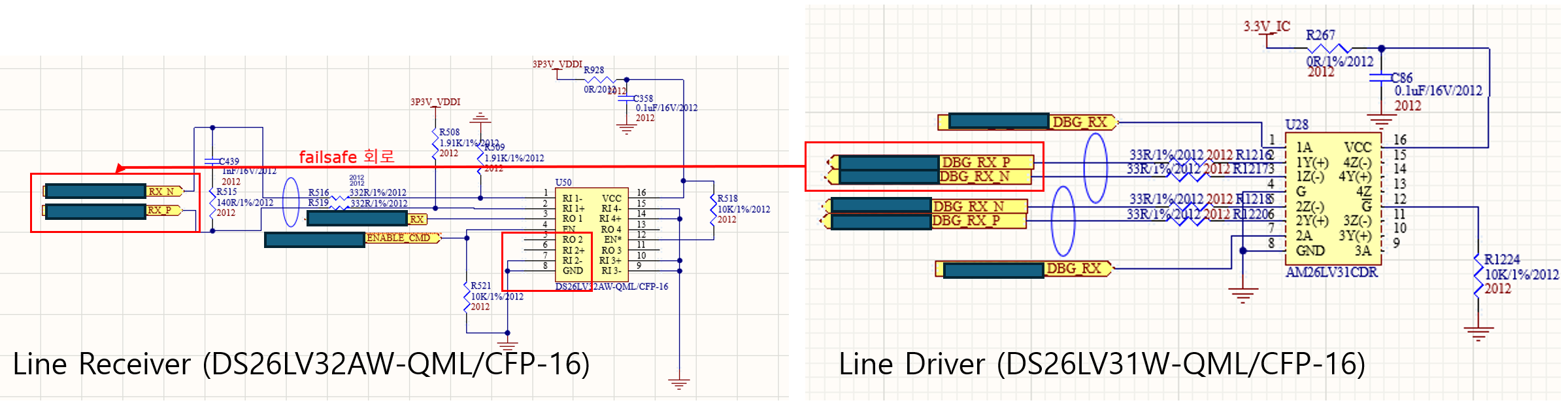
image.png


3. in below circuit, RO3, RI3+ connected to GND, RI4 normal operation.
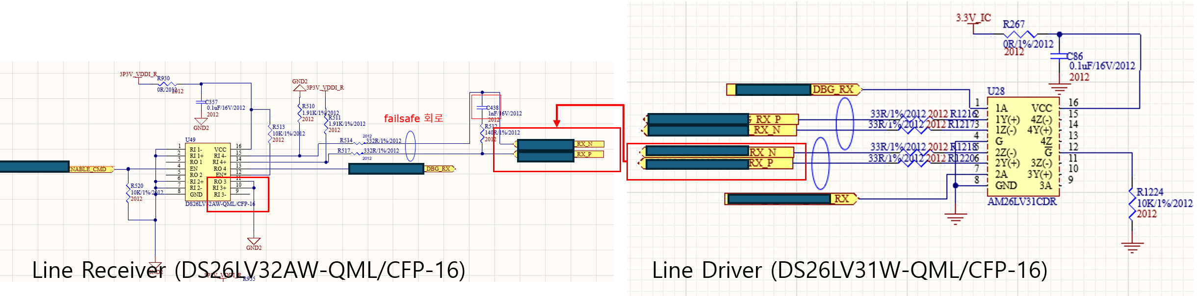
image.png


Thanks.

  • Hi David,

    The pin labels and pin numbers you are using do not line up with the datasheet.

    • Pin 5 is RO2
    • Pin 6 is RI2+
    • Pin 7 is RI2-

    Please clarify exactly how each pin is configured in the customer system. Each unused input should be tied to GND. Outputs should be left open. 

    Also please provide a waveform using an oscilloscope of the RO1, RI1+, RI1- pins while issue is occurring.

    Best,

    Ethan

  • Let me re-explain the situation
    Issue: At U50, RO1 (#3) fails to output despite valid RI1- (#1) and RI1+ (#2) inputs.
    • Case 1: When RO2 (#5) and RI2+ (#6) are directly connected to GND, RO1 (#3) operates normally.
    • Case 2: When RO2 (#5) is pulled down (10k) or left open while RI2+ (#6) is at GND, RO1 (#3) produces no output.

    RO1 functions correctly only when RO2 is directly tied to GND, but fails if RO2 is pulled down or floating (open)

    • RO2(#6), RI2+(#7) connected to GND -> RO1 normal output
    • RO2(#6) pull down(10k), RI2+(#7) to GND -> RO1 no output

    Can you get a scopeshot of the working and not working case? Please provide RIN+/RIN-/ROUT and math function of RIN+MINUS RIN-.

    Do you have a strong GND connection on your PCB for pin8? Do you have a picture of the top layout?

    -Bobby

  • "Sorry, no waveforms available. Previous test results:
    • RIN+/RIN-: Same waveforms.
    • ROUT (NG): No output change.
    • ROUT (OK): Normal output."

  • + GND is strong GND

    "I find it confusing that ROUT on Channel 2 needs to be tied to GND for proper operation, even though only Channel 1 is being driven." 

  • Something else in your schematic/layout must not be configured correctly. Unused outputs should not be tied to GND. 

    We have seen a case where the GND pin (pin 8) was not properly connected to the GND plane. Yet, when other input/outputs where grounded, the transceiver was able to function. This is just an educated guess, but until we get waveforms, we can't provide much more assistance. 

    Additionally, in your schematic, some of the pins are not numbered correctly. For instance, on the DS26LV13 driver pins 15 through 13 do not match the datasheet. I would double check all pins are connected properly, and check that they match the datasheet.