This thread has been locked.

If you have a related question, please click the "Ask a related question" button in the top right corner. The newly created question will be automatically linked to this question.

TMDS181: Fail in HDMI compliance test

Part Number: TMDS181

Dear TI team:

We are using TMDS181 in order to improve HDMI output. But now we are facing HDMI compliance test fail issue.

Our produce's HDMI out support up to 4K30hz. When it works in 4K mode, the test pass. But when it works in 1080P mode, the single-ended voltage is always below the limit value, while the mask test is pass.

   -- in 1080P mode, the lower limit value is 2.7V, but the test value is always about 2.6V. Pls see below pic.
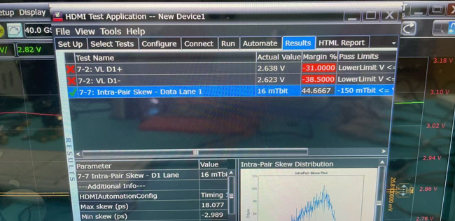
image.png


Here is our configuration about TMDS181:

VSADJ=7.06K

PRE_SEL = No Connect

TX_TERM_CTL = 75 to 150 Ω


I have tried to modify transmit termination and swing, it works, but when it pass the single-ended voltage test, the eye pattern mask test will fail.

Please guide us how to modify? Currently, it is operating in GPIO mode, and if need, it can be work on I2C mode.

  • Hi,

    Please leave TX_TERM_CTL as NC so it can change its termination based on HDMI1.4 and HDMI2.0. The 75ohm to 150ohm is for HDMI2.0. The open and 150-300ohm termination is for HDMI1.4.

    You can then tune the VSADJ resistor value to find a resistance that can pass both the VL and VSWING compliance requirement. If you reduce the VSADJ resistance, then the VSWING will increase, but VL will decrease. If you increase the VSADJ resistance, then the VSWING will decrease, but VL will increase. The key is to find a resistance that can meet both requirement.

    Thanks

    David

  • Hi,

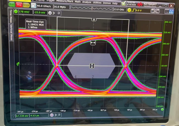
    Re VSADJ resistor, we will try step by step. But re TX_TERM_CTR, we set it NC at first, but its performance was not satisfactory. pls see below result, if any other related configuration? pls advice.

    TX_TERM_CTR = NC

    TX_TERM_CTR = 150 Ω to 300 Ω

    TX_TERM_CTR = 75 Ω to 150 Ω

  • Hi,

    Can you please share the Keysight HDMI compliance with these eye diagram? The first eye diagram looks to be ~5Gbps and the third eye diagram looks to be 3Gbps, do you have the eye diagram of the same data rate and different TX_TERM_CTR?

    Thanks

    David

  • Hi,

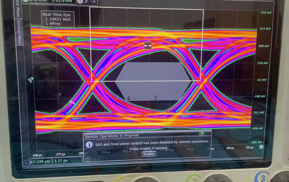
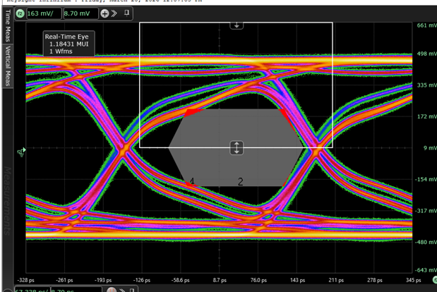
    The below pics are all tested in 3840-2160-30Hz, maybe something different in SWING. Pls have a look. 

    I found when set it as automaticall, the eye is not very clear. No matter in 1080P or 4K mode. 

    When TX_TERM_CTR is setted as "150 Ω to 300 Ω " , it should fit for our application- up to 4k30hz, and VL always pass, but I found the eye is not good enough in 4K, it always touch the mark, even I increase swing.

    When TX_TERM_CTR is setted as "75 Ω to 150 Ω " , the eye is very clear, eye mark test is no problem, but VL will be too high in 1080P, as I described above.

    So if TX_TERM_CTR can be setted to "150 Ω to 300 Ω " when 1080P, and be setted to "75 Ω to 150 Ω" when 4k, it will be best.  Do you think is it possible? 

    Now we are working on looking for a suitable VSADJ - increase to improve VL, and set TX_TERM_CTR to "75 Ω to 150 Ω, then modify SWING by I2C to pass the test, do you see any problem?

    TX_TERM_CTR = NC

    TX_TERM_CTR = 150 Ω to 300 Ω

    TX_TERM_CTR = 75 Ω to 150 Ω

  • Hi,

    The TX_TERM_CTR = NC should be used for data rate < 1.65Gbps, 150-300ohm should be used for 1.65Gbps <= data rate < 3.4Gbps, and 75-150ohm should be used for 3.4Gbps <= data rate. For 4k@30Hz, you should use the 150-300ohm termination. When I am looking at the 3G eye diagram, I am seeing signal attenuation as the eye shows a very slow ramp time. If you are using the ESD diode protection on the output, can you check its line capacitance? And if possible, you can replace the ESD with lower line capacitance which will help with the ramp rate and enable you to pass the eye diagram.

    For VSADJ and in the I2C mode, tuning the resistance will give you the default VSWING. On top of it, you can write to register 0x0C to further increase or decrease the VSWING.

    Thanks

    David

  • Hi 

    Thanks for your advics. We will have a try.

    Re the ESD, we are using ESD8004, attached the datasheet for you reference, its cap is about 0.3pF, do you think it is too high?

    ESD8004.PDF

  • Hi,

    With the ESD diode line capacitance of 0.3pF, it should be enough to support 3Gbps data rate. Any chance you can share your layout?

    Thanks

    David

  • Hi David:

    I can send to you through direct message, please accept my friend request.

  • Hi,

    I accepted your request, you can send me the schematic and layout in a private E2E message.

    Thanks

    David