This thread has been locked.

If you have a related question, please click the "Ask a related question" button in the top right corner. The newly created question will be automatically linked to this question.

DS90UB928Q-Q1: Key Datasheet parameters for Jitter Measurements

Part Number: DS90UB928Q-Q1

Hi,
We have been conducting Eye Diagram measurements on the FPD-Link-III transmission line at Des.

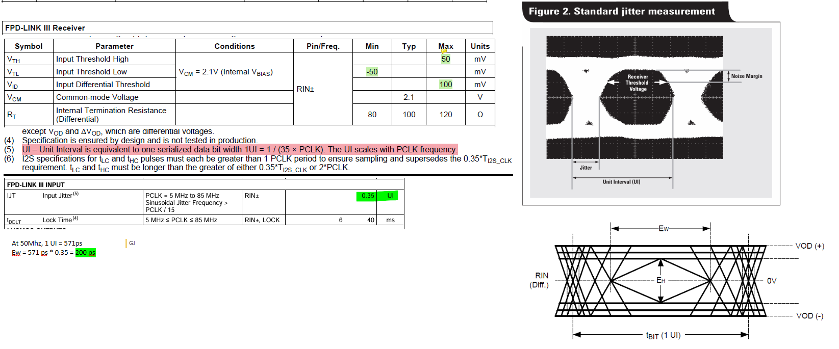
Looking at the datasheet we are trying to identify the key parameters for comparion for both the 'Noise Margin' and 'Receiver Threshold Voltage'. I have attached a image of the values we have identified thus far. 

For the Noise Margin Input Threshold High & Low (Vth & Vtl) is stated as +/- 50 mV so this satifies this.

For the Receiver Threshold Voltage we have identified  the parameter IJT Input Jitter of 0.35 UI. 1UI = 1/(35 x PCLK), At 50 MHz = 571 ps. Therefore Diff Output Eye Height (Ew) = 571 ps * 0.35 = 200 ps. Is this parameter correct for the threshold ?
LVDS Levels - OneNote.png

  • Hi Lee,

    For the Receiver Threshold Voltage we have identified  the parameter IJT Input Jitter of 0.35 UI. 1UI = 1/(35 x PCLK), At 50 MHz = 571 ps. Therefore Diff Output Eye Height (Ew) = 571 ps * 0.35 = 200 ps. Is this parameter correct for the threshold ?

    This understanding of thinking is correct, calculating the data rate = 35 * PCLK, if 50 MHz then data rate is 35 * 50 = 1.750 Gbps

    1 UI = 1/(1.750 Gbps) = 571.428 ps

    EW should actually be Eye-Width, which is what is accounted for after input jitter is accommodated for. The jitter should actually be characterized as the width of the eye:

    So the measured width from your collected diagram should be under 0.35 UI, or this length should be less than 200 ps.

    Best,

    Miguel