This thread has been locked.

If you have a related question, please click the "Ask a related question" button in the top right corner. The newly created question will be automatically linked to this question.

DS90UB983-Q1: DS90UB943A-Q1,MODE_SEL2 pin setting issue?

Part Number: DS90UB983-Q1

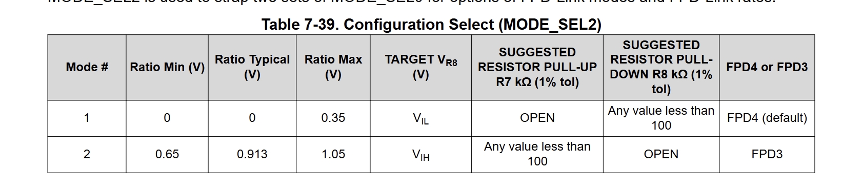
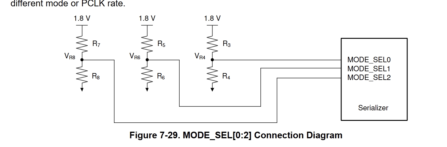
DS90UB983-Q1, Configuration Select (MODE_SEL2) table: when selecting FPD3 mode, the typical voltage value of this pin is 0.913V. However, the description later states that pull-up resistor R7 can be any value less than 100, and pull-down resistor R8 is OPEN. What is the correct voltage for this pin? Is it 0.913V or 1.8V?
983-1.png


983-2.png


  • Hi Fei,

    when selecting FPD3 mode, the typical voltage value of this pin is 0.913V. However, the description later states that pull-up resistor R7 can be any value less than 100, and pull-down resistor R8 is OPEN.

    Sorry for any confusion, the Ratio Typical should be a nominal value, not associated with specific voltage seen at the pin. This voltage you are looking for will actually be TARGET VR8, which will be VIH, which is range 1.1115V to 1.89V.

    The Ratio Min, Typical, and Max values are all related to the resistor ratio, but simply this configuration is intended to be either routed to VIH to select FPD3 or routed to GND for FPD4 mode.

    Ideally, it should try to target 1.8V.

    Best,

    Miguel

  • Thank you very much for your reply. The display is 1080P/60Hz. Does selecting 0.875 Gbps for MODE_SEL0meet the requirements?

  • For DS90UB983 with MODE_SEL0=1 and FPD-Link rate of 0.875 Gbps, does this satisfy the bandwidth requirement for 1080P/60Hz display?

  • Hi Fei,

    I'm assuming the display has a typical resolution of 1920 x 1080 at 60 fps, when including blanking of 1.1 this translates to 136.8576 MHz PCLK.

    1920 * 1080 * 60 * 1.1 (horizontal blanking and vertical blanking estimated to be 10% of active video resolution) = 136,857,600 Hz

    The data rate in FPD4 mode would be PCLK * bpp, assuming 24 bpp this would be 136.8576 MHz * 24 bpp = 3.285 Gbps.

    The data rate in FPD3 mode would be PCLK * 35 (FPD3 has 35-bit frame), this would be 136.8576 MHz * 35 = 4.790016 Gbps

    I think the FPD-Link rate needs to be at least 6.75 Gbps in FPD4 mode (due to 128 / 132 overhead), and for FPD3 the device will need to override the default FPD3 PLLs for this PCLK, since it needs a much higher data rate than the selections in MODE_SEL0.

    Typically, the Script Gen Tool will generate 983conf.py files that will automatically correct this configuration.

    Please let me know if you have any further questions!

    Best,

    Miguel

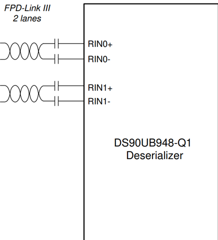
  • Since the panel side uses the 948 chip, we currently select FPD-Link III mode with one LINK channel. Which rate should be chosen for MODE_SEL0 to meet the requirements of a 1080P display?

  • Hi Fei,

    The PLL for the 983 in FPD3 mode will be programmed with the intended value using Script Gen Tool, which is how the 983 outputs PCLKs and resolutions higher than the 85 MHz offered from the default MODE_SEL0 options.

    This is the method in which the 983 should be initialized every time also.

    You can set it to any rate initially to allow an initial link between the devices, but the 948 will automatically reconfigure to the programmed 136.8576 MHz PCLK rate as long as it is in Dual FPD-Link III configuration to accommodate 96 MHz < x < 196 MHz PCLK.

    If you need further clarification, please let me know.

    Best,

    Miguel

  • Thanks for your explanation. To update: the display resolution is 1920×720 at 60 Hz.
    Is my understanding correct:When MODE_SEL2 = 1, the mode is FPD3 protocol. Currently, a single FPD-Link channel is used for output. None of the default values in the MODE_SEL0 table can meet the requirements. Instead, the software script generation tool will automatically generate the 983conf.py configuration file to complete automatic calibration of the above parameters.
    For the hardware side: which voltage-divider resistor should be selected for the MODE_SEL0 pin? In other words, which of the 8 entries in the table should be chosen?
    Thank you.

  • Hi Fei,

    Thanks for your confirmation of the understanding and updating about the display resolution!

    To update: the display resolution is 1920×720 at 60 Hz.

    Understood, a new estimate of the PCLK will be 1920 * 720 * 1.1 * 60 = 91.2384 MHz.

    This is sufficient for single lane FPD-Link III mode.

    Is my understanding correct:When MODE_SEL2 = 1, the mode is FPD3 protocol. Currently, a single FPD-Link channel is used for output. None of the default values in the MODE_SEL0 table can meet the requirements. Instead, the software script generation tool will automatically generate the 983conf.py configuration file to complete automatic calibration of the above parameters.

    This understanding is correct. 91 MHz or above is not a default configuration, the highest default is 85 MHz, so the Script Generation Tool will override the PLLs to the desired rate for the FPD-Link III connection as you have mentioned.

    For the hardware side: which voltage-divider resistor should be selected for the MODE_SEL0 pin? In other words, which of the 8 entries in the table should be chosen?

    Out of the 8 options you may select the default Mode #7 as a placeholder since it has the highest data rate with FPD TX Port 0 selected.

    Please let me know if you have any further questions!

    Best,

    Miguel

  • Thank you for your explanation. If we switch to a 1080P/60Hz display, the maximum frequency in the MODE_SEL0 table is 85MHz. For hardware, none of the entries in the table can meet the requirement. Is it still recommended to select entry #7 in the table, which corresponds to the highest 85MHz?

  • Hi Fei,

    It is still recommended to use entry #7 to initially establish FPD-Link III, then override through software upon 983 initialization, whether using 1080p or 720p.

    Thanks for confirming. 

    Best,

    Miguel