DP83867IR: DP83867 PHY Address Strapping Issue

Part Number: DP83867IR

Hi,

I’m currently troubleshooting an issue during the power-up sequence of the DP83867IR, specifically related to the sampling of the PHY address strapping pins. We are using the PHY in 3-supply mode, with VDDIO at 1.8 V.

We observe two different power-on behaviors:

Working Case

Full Trace eth_2-5v_1-8v_reset_passing_zoomedout.png

Power Sequenceeth_2-5v_1-8v_reset_passing_zoomed.png

Reset
eth_2-5v_1-8v_reset_passing.png
  • The 1.8 V rail ramps up and settles in ~0.5 ms.
  • The 2.5 V rail begins ramping ~0.1 ms after the 1.8 V rail starts ramping (i.e., before 1.8 V has settled) and settles in ~1.5 ms.
  • Both rails are stable well before reset is released (~200 ms later).
  • In this case, the PHY initializes correctly with the expected address (00001).
  • The RX_D0 strapping pin remains high for ~60 ms after reset release before being pulled low.

Failing Case

Full Trace

eth_2-5v_1-8v_reset_failing_zoomedout.png

Reset

eth_2-5v_1-8v_reset_failing.png

  • The power rails ramp in the same order and with similar timing.
  • However, reset is released much later (~2.5 s after both rails are stable).
    (This delay is arbitrary; the same issue occurs for reset delays ≥ ~300 ms.)
  • In this case, the PHY initializes but latches the incorrect address (00000).
  • Notably, RX_D0 is pulled low immediately as reset is released, even before reset reaches 1.8 V.

Debugging performed (failing case):

All observations below are consistent with the working case unless noted otherwise:

  • Isolated RX_D0 from the SoC by cutting the trace between the SoC and the strapping resistors. The behavior remains unchanged, indicating the DP83867 is pulling the line low.
  • Verified MDIO/MDC activity: no traffic is present prior to SoC boot, confirmed via oscilloscope.
  • Checked INT/PWRDN#: remains high throughout the sequence as expected.
  • Checked XO and CLK_OUT: clock is present once power rails are up, even while reset is asserted, and remains stable well before reset release.

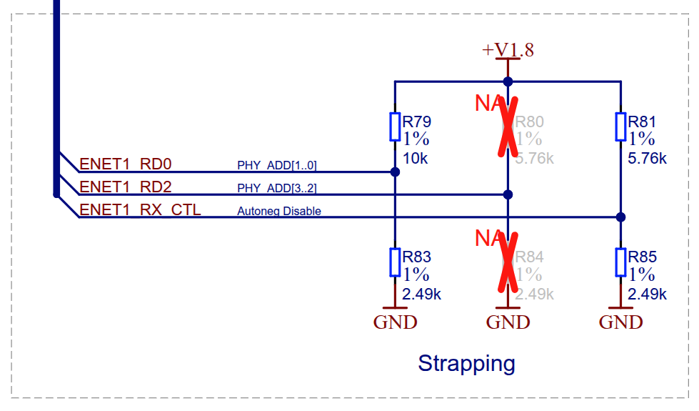
In both cases our strapping looks as follows:

strapping_circuit.png

Question:

Do you have any guidance on what could cause RX_D0 to be driven low at reset release in the failing case, resulting in the incorrect strap reading?

Specifically, is there any dependency on reset timing relative to power stability that could explain this behavior?

  • Hi Joseph,

    RX_D0 will apply a 9k pulldown while the PHY latches in the strap setting. This should form the correct resistive divider with your external strap to place the RX_D0 pin in Mode 2 (in your case). Once the strap is latched in, the PHY will pull this pin low with a much stronger termination meant for RGMII signaling.

    It seems from your waveform capture that this happens almost immediately after RESET rises when RESET is delayed >300ms. This would align with the T2 RESET timing in section 6.7 of the datasheet:

    When RESET is not delayed, you get about 60ms of latch-in time before the RX_D0 becomes a transmitter. In this case it appears in the magnitude of the T2 powerup timing for latch in:

    I wouldn't expect a delay of the reset in-itself to affect the strap latch in value. Let me try and reproduce this on an EVM in our lab and let you know what I see.

    Best,

    Shane

  • Hi Shane,

    Thank you for the quick response. I also have some additional information that may help with reproducing the issue.

    On the affected product, we have two Ethernet PHYs: a DP83867IRRGZR and a DP83867ISRGZ. The DP83867IRRGZR is the device for which I previously shared traces with the strapping issue.

    For the DP83867ISRGZ, we follow a similar power-up sequence and observe the strapping sequence occuring similar to the reset timing, but with what looks like the "Post RESET stabilization time" happening before the latch-in reading, regardless of how long the device is held in reset. The main difference in power sequencing between the two devices is that, for the DP83867ISRGZ, the 2.5 V rail is up and stable before the 1.8 V rail, with the 1.8 V rail settling approximately 3 ms later.

    Below are some snapshots showing the working sequence on the DP83867ISRGZ:

    Thank you and looking forward to seeing the results of the experiment on the EVM.

  • Hi Joseph,

    Thanks for the details, my plan is to set our DP83867-R-EVM into strap mode 2 on RX_D0 similar to your use-case. This board uses 2-supply mode so it will not be exactly 1:1 with your design, but may help give us a scope of the problem.

    Best,

    Shane

  • Hi Joseph,

    I tested our EVM in the lab and am not able to reproduce this issue so far. I strapped RX_D0 into mode 2 using resistors and am able to read at address 0001. Here is what I saw in the scope when releasing RESET at 600ms:

    Purple (2.5V and VDDIO), Yellow (RX_D0), Green (RESET).

    This seems to follow the waveform in your failing case:

    eth_2-5v_1-8v_reset_failing_zoomedout.png

    Out of curiosity, is your DP83867 using the VDDA1p8V pins, or is the 1.8V rail in your measurements only the VDDIO? Furthermore, do you see this issue on all of your boards or a certain percentage?

    Best,

    Shane

  • Thank you for the quick response!

    Out of curiosity, is your DP83867 using the VDDA1p8V pins, or is the 1.8V rail in your measurements only the VDDIO?

    For us, VDDIO and VDDA1P8 share the same 1.8V rail. I probed the rail a bit far from the PHY though, I will see if I can get a more direct measurement on the PHY pins to make sure there are no discrepancies there. 

    Furthermore, do you see this issue on all of your boards or a certain percentage?

    We are seeing it on 100% of the boards.

    Would it be possible to also share the zoom-in of the trace at the following 2 points:

    1. Where the 2.5V rail comes up.

    2. Where reset is released. 

    In our failing case, I’ve also noticed that the strapping pin is pulled down closer to ~1.0 V, which is nearer to the third rail. This makes me wonder whether there could be some interaction introduced by the additional rail in our 3-supply setup.

    Additionally, since your configuration uses a 2.5 V VDDIO while ours uses 1.8 V, I’m also considering whether this difference could be contributing to the behavior we’re seeing.

  • Hi Joseph,

    Let me run this test again with zoom-ins on the 2.5V rail and reset release. I agree that the 1.8V rail could be making a difference here. Unfortunately I don't have a convenient way to power sequence multiple rails of different voltages so adding in the 1.8V rail will take time.

    Please note I will be out of office from tomorrow through Tuesday of next week

    Best,

    Shane

  • Hi Joseph,

    Here is a zoomed in image of the RESET timing. RESET is green, RX_D0 is yellow, and 2.5V is purple

    Here is the zoomed image of the powerup timing.

    Best,

    Shane

  • Hi Shane,

    I'm not seeing the images of the zoomed in traces in the forum, and when I try to open the images themselves in a new tab I get the below message:

    I am able to see the previously attached images both in the forum and when attempting to open them in their own tab.

  • Hi Joseph,

    I get the same issue, not sure why this happened. Here are the photos:

    Powerup timing:

    Reset timing:

    Hopefully these do not have problems showing.

    Best,

    Shane

  • Thank you, I was able to see the traces this time. 

    The zoomed in trace is intresting. It looks like the strapping resistor is pulled down around ~800-900mV, which is consistent with what we observe. Do you have any insight into why it gets pulled down so early? Is the reset tied to the VDD1P0/1P1 rails?

    I also noticed that the rise time in the traces you provided on the reset line looked longer than ours, so I played with the rise time of the reset line, making it both shorter and longer, but the issue was still seen.

    In addition we were able to simplify the reproduction steps. Performing a warm reset also causes the DP83867 to strap to the wrong address in our setup. 


    Do you have any thoughts based on the above on where I could investigate next? I was also wondering whether you’re planning to attempt reproduction with the addition of the 1.8 V rail. In the meantime, I’ve ordered a DP83867IR EVM to see if I can reproduce the issue with that setup.

  • Hi Joseph,

    Its good that you will have an EVM to correlate with. As for what you can do on your current board, I'd check that the clock is supplied at powerup to align with the datasheet timing diagram. If there is a way to adjust the power sequence at all, its generally better to avoid pedestal voltages and to ramp all rails at the same time. I see a few zoomed in power sequences for working cases with different 1.8V rail behavior. Was there an image for the non-working case that is this zoomed in?

    eth_2-5v_1-8v_reset_passing_zoomed.png

    Apologies but I haven't put together a test with the 1.8V rail added. The issue I was struggling with on my side is precisely timing a powerup sequence with two supplies (using the on-board 5V LDO for 2.5/1V and manually adding in the 1.8V rail via power supply). Do you have a method to time the power ramp sequence precisely? 

    Best,

    Shane