This thread has been locked.

If you have a related question, please click the "Ask a related question" button in the top right corner. The newly created question will be automatically linked to this question.

DS160PR410: CTLE

Part Number: DS160PR410


Regarding the CTLE bandwidth adjustment:

1. What are the differences between the four options?

2. Which part of the PCIe signal will be affected?

3. In Pin Mode (CTLE strength is adjusted using an external resistor), which of the four is the default? 

ctle.jpg

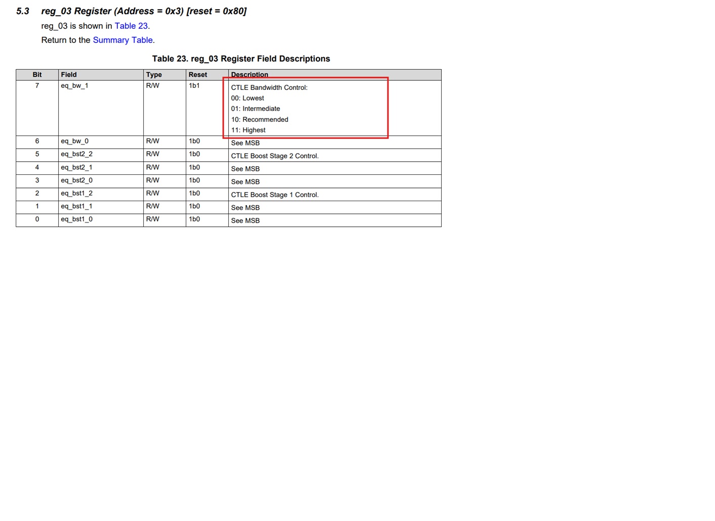
If the bandwidth is adjusted to 00 (Lowest), which side of the PCIe signal will be affected?

If you have any documentation explaining this, could you please provide it for our reference?

Reason: Our current testing shows that the Pin Mode setting is PASS after adjustment, but when applied to I2C/SMBUS control, it results in NG (Not Acceptable).

We need to adjust the CTLE Bandwidth Control value from 10 (Recommended) to 00 (Lowest) for it to pass the test.

We have also confirmed that all other corresponding values ​​are consistent with the Pin Mode setting and are correct.

Thank you for your assistance.

  • Hi Gareth,

    We don't recommend adjusting CLTE bandwidth control register. Please keep it at default value of 10. 

    3. In Pin Mode (CTLE strength is adjusted using an external resistor), which of the four is the default? 

    In pinmode, default value for CTLE bandwidth is 10 also. 

    Reason: Our current testing shows that the Pin Mode setting is PASS after adjustment, but when applied to I2C/SMBUS control, it results in NG (Not Acceptable).

    Please ensure your SMbus EQ programming sequence follows table 8 in the programing guide. The CTLE index and EQ settings shown in table 8 match with the Pin Mode EQ settings in the datasheet.

    Best,

    Charles