This thread has been locked.

If you have a related question, please click the "Ask a related question" button in the top right corner. The newly created question will be automatically linked to this question.

TMDS1204: Request for HDMI 2.0 TX Schematic Review and Design Validation

Part Number: TMDS1204
Other Parts Discussed in Thread: TDP1204, TDP2004

Dear TI Support Team,

I am currently working on a hardware design involving an HDMI 2.0 transmitter and would greatly appreciate your expert review and guidance on my schematic. The design is intended to support high-speed video transmission compliant with HDMI 2.0 specifications, and I want to ensure robustness, signal integrity, and compliance with TI’s recommended design practices.

Project Overview:

  • Application: HDMI 2.0 Transmitter (TX)
  • Target Resolution: Up to 4K @ 30Hz
  • FPGA/Controller: PolarFire FPGA
  • HDMI TX Device: TMDS1204
  • Power Supply Rails: 3.3V

Request for Review:

I kindly request your support in reviewing the following aspects of my schematic:

  1. Power Supply Design
  2. High-Speed Signal Routing
  3. ESD and Protection
  4. DDC / HPD / Control Signals

I have attached the schematic PDF along with relevant design notes for your review.

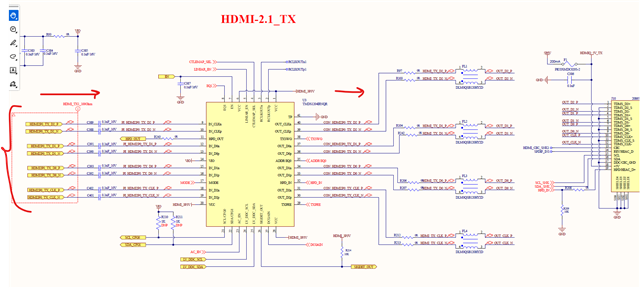
SCHEMATIC_HDMI-2.1_TX.PDF 

Please let me know if any additional information is required from my side. Your feedback will be extremely valuable in helping me finalize a reliable and high-performance design.

Thank you very much for your time and support.

Best regards,

Milan

  • Hi Milan, 

    Below are my comments:
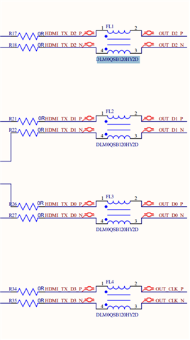
    1. Please co-lay 0 ohm resistors and common mode choke in the layout:

    2. The CMC cut off frequency is too low (2GHz). We recommend the cut off frequency to be three times the Nyquist frequency of the data lane so 9 GHz. 

    3. ESD diodes used for HDMI may have too high clamping voltage (8.8V) for our device to survive ESD events. Please refer to ESD diodes like PUSB3FR4Z for lower clamping voltage ESD diodes. 

    Best,
    J

  • Hello,

    Thank you for the quick response. 

    Point 1 and 2 not clear understanding for me.

    Are you suggested schematic level changes? If yes then please share exactly what i have to change and what about rest of the circuit?

    Everything looks okay ?

  • Hi Milan, 

    Point 1 is for layout. We typically recommend customers to co-lay the pads for CMC and the 0 ohm resistors in the layout so they can replace the CMC with a 0 ohm resistor if needed. This is because CMC may impact HDMI's signal integrity. 

    Point 2 is not for schematic change, but for BOM change. The CMC used in this schematic has a low cutoff frequency and we recommend customers to use CMCs with higher cutoff frequency (9GHz for HDMI 2.0). 

    Otherwise, the schematic itself looks good (except for point 3). 

    Best,
    J

  • Hi,

    Point 1 For now we have released our design for the prototype. So that opinion will not be able to be added.

    Point 2/3 We have used a CMC & ESD diode in the eval board schematic (SLLU341).

    So for prototype purposes, is that okay to go & do you really think that it will work for 12G as per my schematic design?

    Regards,

    Milan

  • Hi Milan, 

    CMC and ESD diodes both should be fine. It is more of a recommendation for our customers based on our past experiences. I do not anticipate any functional issue. 

    Best,

    J

  • Hi,

    We have received the prototype board and conducted testing on the HDMI TX. However, it is not functioning as expected. The monitor is unable to detect the HDMI TX signal.

    Kindly advise on the next steps or any checks we should perform to troubleshoot this issue.

    we are waiting for your reply ASAP.

    Thanks,

    Milan

  • Hi Milan, 

    Have you tried different monitor and cable?
    Also, can you probe HPD signal to ensure that it is high and then see if there is any DDC buffer activity on both high voltage and low voltage side?

    Best,
    J

  • Hi,

    I have tested with two different monitors and two different cables.

    The HPD signals are as follows:

    • HPD In: High

    • HPD Out: High

    I have not yet checked the DDC activity. Could you please clarify what exactly needs to be verified on the DDC lines and what behavior is expected on those pins?

    We are currently using strap mode—do you think this could be causing any issues?what we have missed?

    Also, we are operating at a 6G data rate. Based on this configuration, do you see any potential concerns?

    Additionally, we are planning to switch to I2C mode. Could you please provide the list of registers that need to be configured?

    Thanks,
    Milan

  • Hi Milan, 

    Could you please clarify what exactly needs to be verified on the DDC lines and what behavior is expected on those pins?

    We are expecting to see bus activity once the hdmi cable is plugged in. If there is no bus activity, there will be no display. 

    Is it 6G TMDS or FRL? 

    You may consider increasing the EQ setting and changing to linear mode instead of limited mode. 

    I suggest to look at 7.4.1.1 section in the datasheet for the i2c configuration guide. 

    Best,
    J

  • Hi,

    I have not configured any specific settings for TMDS or FRL, as I am currently using HDMI 2.0. Is there anything that needs to be set for this? We previously shared the schematic with you—could you please review it and suggest what changes we missed? What setting are required for HDMI 2.0?

    Also, what changes are needed to operate in linear mode? My understanding is that it should work in limited mode—could you please confirm?

  • Hi,

    We have two issues and would appreciate your guidance:

    1. HDMI Resolution Mismatch
      We are currently receiving HDMI video at a resolution of 1922x1080p @ 59 Hz, while the input provided is 1920x1080p @ 60 Hz.
      This behavior is observed when the IC is configured in strap mode, and due to this mismatch, the output is not detected on all monitors.

    Could you please confirm:

    • Why this resolution/timing mismatch is occurring?
    • Whether this could be due to incorrect configuration or internal scaling?
    • How we can ensure proper detection across all monitors?
    1. I2C Mode Issue
      When switching to I2C mode, we are not receiving any response from the IC.
    • The MODE pin is left floating for I2C selection.
    • The configured I2C address is 0x5D (as per ADDR pin configuration).

    Could you please advise:

    • If any additional hardware configuration is required for I2C mode (e.g., pin states)?
    • Whether the MODE pin should be explicitly driven instead of left floating?
    • Any initialization sequence required after switching to I2C mode?

    We would appreciate your guidance on both issues.

    Thank you.

    Best regards,
    Milan

  • Milan

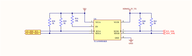
    The DDC bus uses the I2C protocol. When a monitor plugged into the HDMI receptacle, the source uses the DDC bus to read monitor vendor/model ID, resolution supported, etc. The source also uses the DDC to communicate to the monitor when switching between HDMI1.4 and HDMI2.0. The TMDS1204 uses its LV_DDC_SDA/SCL to snoop this bus and configure itself automatically between the HDMI1.4 and 2.0. You can use an I2C decoder or analyzer to read the DDC communication. When I am looking at the schematic, I noticed that you have pullup on LV_DDC_SDA/SCL as shown below. Please remove R38 and R39 since TMDS1204 has internal pullup. 

    The TMDS1204 as a re-driver has no concept of resolution, so when you say "We are currently receiving HDMI video at a resolution of 1922x1080p @ 59 Hz, while the input provided is 1920x1080p @ 60 Hz.This behavior is observed when the IC is configured in strap mode, and due to this mismatch, the output is not detected on all monitors", what does this mean? 

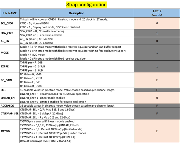
    The design itself is DC-coupled to the HDMI receptacle. But AC_EN pin is being pulled high for AC coupled output. You would need to pull it low for DC coupled output.

    For I2C mode, you would leave MODE pin floating. But before we switch to the I2C mode, can we stay in the pin strap mode and make modification to the DDC and AC_EN pin first?

    Thanks

    David

  • Hi,

    You suggested making two hardware changes:

    1. Remove the LV I²C pull-up resistors.
      Note: We are not currently doing anything on the DDC I²C lines—just connecting them directly to the source.

    2. Set the AC_EN pin to low.

    Will these changes resolve the issue?

    If the problem still persists, what should be the next steps in I²C mode? Please suggest the that options with required setting. 

    Additionally, I would like to mention that in strap mode we are able to receive video over HDMI. However, when we increase the data rate slightly at the same resolution, the HDMI signal is no longer detected. Do we need to update the strap settings to support higher data rates?

    Thanks.

  • Milan

    The AC_EN would impact the main link signaling, so I would make sure the AC_EN gets pulled low in the pin strap mode. 

    If we are looking at the main link signal quality first, then I would also change the CTLEMAP_SEL to "F".

    You can then tune EQ0 and EQ1 to help compensating the signal quality at the TMDS1204 input.

    Because TMDS1204 is being configured as a limited re-driver, you can also tune TXSWG and TXPRE to compensate the signal quality at the TMDS1204 output. If you have a high speed scope that can measure the output signal, then this will really help when tuning the RX EQ0/EQ1 and TXSWG and TXPRE.

    For I2C configuration, I would follow the example in section 7.4.1.1 HDMI 2.1 Source Example with DDC Snoop Disabled and DDC Buffer Disabled as a starting point. Please make sure to read back the registers after writing to make sure the I2C read/write is working correctly.

    Thanks

    David

  • Hi,

    I will test all options in strap mode, which you have suggested, and see what happens.

    In I²C mode, we are unable to perform write and read operations. Using Aardvark, we are trying to read the ID, but nothing happens.

    Could you please suggest if any hardware configuration is missing or if something needs to be adjusted for I²C?

    We are so close, just something missing...!!

    Thanks,

    Milan

  • Milan

    With 20k pulldown on ADDR, this will set the address to 0x5D. And with MODE pin floating, then this will enable TMDS1204 in the I2C mode. 

    Can you populate R31 and R32 with 4.7k and disable the I2C pullup in the Aardvark controller? 

    You can also replace R52 with 1k and try with I2C address of 0x5E, does it work?


    Thanks

    David

  • Hi David,

    We have tried all available options in I2C mode which you have given, but we are still unable to getting response from IC. We are trying to read the ID using aardvark but not getting. Could you help us understand what might be causing this issue?

    We then shifted our focus to strap mode and applied the configurations you suggested. However, we are still not achieving the expected higher resolution. Instead of 1920×1080, we are observing a TMDS resolution of 1922×1080.

    Additionally, in HDMI 2.0 mode:

    • When we provide a 1080p 8-bit input from the FPGA, it works correctly.
    • However, when we provide a 1080p 10-bit input, the monitor does not detect any signal.

    Could you please advise on what might be going wrong or suggest further steps to debug this?

    Best regards,

    Milan

  • Milan

    The TMDS1204 does not impact the resolution. If you are sending a 1920x1080 resolution, you will get a 1920x1080 resolution. 

    For the 1080p 8-bit to 1080p 10-bit, this is still below the HDMI2.0 data rate (3.4Gbps <= Data Rate < 6Gbps), so I am not sure what you mean in HDMI2.0 mode. But if we need to work in HDMI2.0 mode, then we need to make sure the TMDS1204 DDC is working correctly so TMDS1204 can automatically switch between HDMI1.4 and 2.0 in pin strap mode. In the I2C mode, you can choose to let TMDS1204 configure itself automatically based on the DDC snoop (same as the pin strap mode) or manually write to register 0x20 to configure TMDS1204 between HDMI1.4 and 2.0. But again, TMDS1204 has no concept of 8-bit or 10-bit, so I wonder if the monitor can support 10-bit?

    For the I2C access, once the MODE pin is floating, and address is correct, then you should able to read/write TMDS1204 registers. Can you share a screenshot of your Aardvark I2C controller SW when doing the read of TMDS1204 register?

    Thanks

    David

  • Hi David,

    What does it mean for DDC to be working correctly?

    Currently, we are not actively driving or configuring the DDC I²C pins—they are only connected to the FPGA bank. Could you confirm if any additional configuration or handling is required on our side?

    Also, could you suggest how we can verify that the DDC is functioning correctly?

    Please let us know if any specific steps or actions are needed from our side.

    Tomorrow i will share the screenshot for I2C mode configuration in Aardwark.

    Thanks,

    Milan

  • Milan

    Below is a high level block diagram of the DDC bus.

    The source (FPGA) and monitor exchanges information with each other across the DDC bus using the I2C protocol. Its primary purpose is to allow the monitor to communicate its capabilities—such as resolution, refresh rate, and color format—using EDID (Extended Display Identification Data). Besides the EDID, there is the SCDC register address offset 0x20 for TMDS configurations between HDMI1.4 and HDMI2.0. 

    • Bit 1: TMDS_Bit_Clock_Ratio
      • 0 -> HDMI1.4
      • 1 -> HDMI2.0
    • Bit 0: Scrambling_Enable
      • 1 -> HDMI2.0

    For more detail on the DDC bus, you can see this video, https://www.youtube.com/watch?v=FpLH4rePvjc 

    So if you try to support different resolution with different monitor, then you nee to have the ability of the FPGA to read the monitor EDID, and communicate to the monitor when switching between HDMI1.4 and 2.0. 

    To verifying this function, you can use an I2C analyzer.

    Thanks

    David

  • Hi David,

    We are able to get video working up to 6G in both configuration modes (strap and I2C).

    However, when we try higher data rates (8G, 10G, and 12G), the monitor does not detect any signal.

    Could you please help us resolve this as soon as possible?

    Additionally, we noticed that in your EVM, all lane connections are swapped, including the P and N lines. Could you clarify why this is required?

    Any additional documents needed to study for that swapping on pins?

    Thank you.

  • Hi,

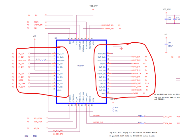
    The EVM was designed to accommodate both TDP1204 and TMDS1204. If you compare the pinout between the two, the lane order are swapped between the two. With the EVM design followed the TDP1204 pinout, when comes to TMDS1204, we basically use its SWAP function as shown below.

    How did you get 6G to work in pin strap and I2C mode? For 8G, 10G, and 12G, I assume these are HDMI FRL. If you read TMDS1204 register 0x31, do you see the FRL_RATE being set correctly?

    Thanks

    David

  • Hi David,

    The issue was due to a pinout mistake on our side—we had made an incorrect connection, as seen in the previously shared schematic.

    We used the swap function to achieve the required pinout as per the reference schematic. Please see attached image for the final connection planned for the next board revision. Could you please confirm if this looks correct?

    With this updated connection, will we still need to use the swap function, or will a direct (straight) connection work?

    Additionally, in the reference schematic, the P and N polarity appear to be swapped. Can you confirm if this is acceptable?

    We also have a question regarding data rate support:
    For higher data rates, can we operate in TMDS mode for HDMI 2.0, or is this chip limited to higher data rates (such as 12G) only in FRL mode?

    Our requirement is to achieve higher data rates in TMDS mode, which is one of the reasons we selected this chip. Please let us know if this is feasible.

    Thanks and regards,
    Milan

  • Milan

    The TMDS1204 is backward compatible to HDMI1.4b and HDMI2.0b. 

    Since it is a re-driver, you can swap the polarity as long as the polarity matches between the input and the output. 

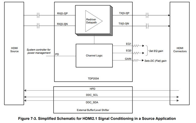
    The TMDS1204 implements a fan-out buffer feature to support applications which the HDMI clock and data on separate paths, and typically this is on a RX design with a FGPA. But in your case which is a HDMI2.1 TX design, why do you use TMDS1204, and not TDP1204? I would also recommend TDP2004 for a AC coupled source side design as its data rate of 24Gbps gives you more margin than TMDS1204.

    Thanks

    David

  • David, 

    Do you mean HDMI2.0 source  application TMDS1204 not suitable for higher datarate above 6G.?

    You will recommend TDP1204 chip for my application?

    Is it direct replacement?

  • Hi,

    TMDS1204 can support higher data rate above 6G. But if you not planning to use its fan out buffer feature, why not use TDP1204? For your TX side design, I would think TDP1204 be a more appropriate choice.

    Instead TMDS1204 or TDP1204, you can also use TDP2004 if you want more margin. 

    Thanks

    David

  • Hi,

    I will definitely go with the TDP1204 chip in the next revision of my design.

    For now, just to validate the hardware and overall concept, I need to use the existing hardware.

    So, could you let me know how we can achieve a higher data rate using a fanout buffer? Will it be used in STRAP or I2C mode, and how would that work?

  • Hi,

    With your design, I don't believe the fanout buffer is needed for higher data rate.

    Below is the I2C code example for manually configure TMDS1204 into HDMI2.1 Gbps FRL 4 lanes.

    With the higher data rate or HDMI2.1 FRL, the source and the monitor need to go through the link training using the DDC bus. Do you know if this is successful?

    Thanks

    David

  • Hi David,

    I was reviewing the TI document TDP1204 (“TDP1204, TMDS1204 Migration from HDMI2.0 to HDMI2.1”), and it mentions that HDMI 2.0 supports only 8-bit color, while we are targeting 10-bit or 12-bit color. Based on this, does it mean we need to use HDMI 2.1?

    Thanks.

  • Hi,

    Correct, for the 4k@60Hz 8bit resolution, the total bandwidth is 17.82Gbps o 5.94Gbps per lane, and this is the max HDMI2.0 data rate.  With 10 bit, the total bandwidth changes from 17.82 * 30 (10bit Color Depth) / 24 (8 bit Color Depth) = 22.275Gbps outside the max HDMI2.0 data rate, so you have to use HDMI2.1.

    Thanks

    David

  • Hi,

    That is for 4K@60hz, but if we use 1080p60hz then it should be work with HDMI2.0. With same chip TMDS1204.

  • Milan

    Your understanding is correct. From bandwidth perspective, both 1080[@60Hz at 8 bit and 10 bit will be running at HDMI1.4. 

    Thanks

    David

  • Hi,

    So in my case we have not getting 1080p60hz 10bit with the same hardware.

    Could you please let me know what exactly we missed?

    Thanks

  • Milan

    Can the monitor support 10-bit resolution? From TMDS1204 perspective, it does not care between 8-bit and 10-bit. The DDC communication should also be the same between 8-bit and 10-bit, stay at HDMI1.4. 

    Thanks

    David