This thread has been locked.

If you have a related question, please click the "Ask a related question" button in the top right corner. The newly created question will be automatically linked to this question.

DS110DF410: DS110DF410 SMBus Master Mode: Register 0xFF and 0x00 Configuration via EEPROM

Part Number: DS110DF410

Dear TI Team,

We are currently configuring the DS110DF410 in SMBus Master Mode using an external EEPROM. We have some conflicting information between the Programming Guide (SNLA323) and the Register Mapping guide (SNLA245):

  1. Register 0xFF (Channel Select): Per SNLA323 (Table 17), we understand that Register 0xFF must be used to select the target channel/page. However, the datasheet indicates that 0xFF is a volatile control register and is not part of the EEPROM-loadable register space.

    • Question: In SMBus Master Mode, how do we correctly structure the EEPROM data image to include the channel selection (0xFF) before writing channel-specific parameters? Does the retimer support executing 0xFF writes directly from the EEPROM sequence?

  2. Register 0x00 (Retimer Reset/Control): We are referencing SNLA245 (Table 15) for register mapping, but Register 0x00 is missing from this table. We need to provide specific values for the retimer control/reset at startup.

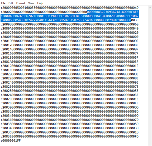
    • Question: Is Register 0x00 accessible for EEPROM loading? If so, what is the correct mapping/addressing required to include it in the EEPROM image for individual channel configuration?Datasheet Table 14.pngSNLA323_Table 17.png

  • Hi Veeramanikandan,

    The programming guide focuses on configuring DS110DF410 using an external SMBus controller (i.e. SMBus slave mode).  The EEPROM configuration will not be sequenced like in programming guide.  For example, steps like CDR reset and release do not make sense with EEPROM configuration.  The EEPROM configuration just allows a one time configuration of register fields included in the EEPROM (marked with "Y" in register map).

    You can use the SigCon Architect GUI to configure registers and generate an EEPROM image.

    Regarding your questions:

    Like you noted, SNLA245 is the primary reference for DS110DF410 EEPROM structure.  You might also reference SNLA244.  Although SNLA244 is targeted at 25G retimers, the EEPROM structure is the same, so there might be some additional valuable examples.

    Register 0xFF (Channel Select): Per SNLA323 (Table 17), we understand that Register 0xFF must be used to select the target channel/page. However, the datasheet indicates that 0xFF is a volatile control register and is not part of the EEPROM-loadable register space.

    • Question: In SMBus Master Mode, how do we correctly structure the EEPROM data image to include the channel selection (0xFF) before writing channel-specific parameters? Does the retimer support executing 0xFF writes directly from the EEPROM sequence?

    In SMBus master mode, the retimer does not implement channel configuration via register 0xFF when reading the EEPROM.  The channel configuration is read in based on the channel register data.  Table 15 in SNLA245 is a good example of this.

    Register 0x00 (Retimer Reset/Control): We are referencing SNLA245 (Table 15) for register mapping, but Register 0x00 is missing from this table. We need to provide specific values for the retimer control/reset at startup.

    • Question: Is Register 0x00 accessible for EEPROM loading? If so, what is the correct mapping/addressing required to include it in the EEPROM image for individual channel configuration?
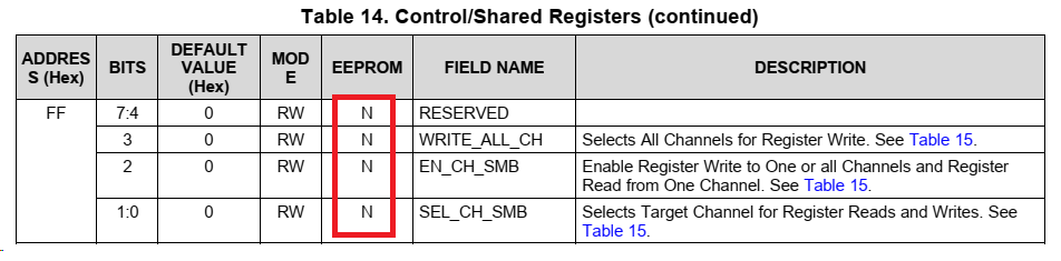
    No, register 0x00 is not configurable through EEPROM.  Please see EEPROM column in the register map.

    Thanks,

    Drew

  • Hello Drew,

    Thank you for the guidance on SMBus Master Mode.

    We are currently troubleshooting a link-up issue on our SGMII interface. While the EEPROM load appears successful,the DONE pin is asserted Low and the status LED is active. we have been unable to establish a link between the processors.

    System Architecture:

    We are utilizing a symmetric signal path across a backplane:

        Path A: Processor 1 (T2080) → Retimer →  Backplane

        Path B: Backplane → Retimer →  Processor 2 (T2080)

        Protocol: SGMII (1.25 Gbps Baud / 1 Gbps Throughput)

        Configuration Source: .hex file generated via SigCon Architect GUI, stored in a 256Kbit EEPROM.

    The Issue:

    Despite the successful EEPROM load, we are unable to establish a link between the processors. The SGMII interface is not "pinging" across the retimer path.

    Request for Information :

        Register Verification: Is there a specific procedure to read back the active register values from the Retimer to verify that the EEPROM data was mapped correctly to the internal registers?

    Read the retimer registers using processor and  control/shared registers can be accessed correctly but observed all channel registers are zeros (channel registers read using 0xFF→0x04 / 0x0C).

        Configuration: I have attached the current register configuration details. Is that any parameters specifically regarding SGMII rate negotiation or any settings are misconfigured for a 1.25 Gbps SGMII signal.

        Reference Configuration: If possible, kindly share a verified reference .hex or .cfg file optimized for SGMII (1.25 Gbps) operation.

    Looking forward to your feedback and technical guidance.

    Best regards,

    Veeramanikandan S

  • Dear Drew, 

    After the EEPROM file is loaded, the Retimer switches from master to slave mode. Under slave mode conditions, the mentioned registers were manually modified and default values for the channel registers are read from the Retimer.

    0x04→0x41 (Self clearing)
    0xff →0x0c (Channels select)
    0x00→ 0x04 (Reset channel registers)

    Default Channel Register Values (Post-Channel Reset):
            0  1   2   3   4   5   6   7   8   9   a   b  c   d   e   f   
    00: 00 00 dc a5 00 00 00 00 00 00 10 0f 08 00 93 69 
    10: 3a 20 a0 30 00 10 7a 36 40 23 00 03 24 00 e9 55
    20: 00 00 00 40 00 00 00 3f 84 40 30 00 72 80 00 06 
    30: 00 20 11 88 bf 1f 31 1f 00 00 a5 00 00 00 80 00    
    40: 00 01 04 10 40 08 02 80 03 0c 30 41 50 c0 60 90   
    50: 88 82 a0 46 52 8c b0 c8 57 5d 69 75 d5 99 96 a5  
    60: 00 00 00 00 00 00 00 20 00 0a 44 00 00 00 00 00  
    70: 03 20 00 00 00 00 b0 c8 57 5d 69 75 d5 99 96 a5
    80: 00 01 04 10 40 08 02 80 03 0c 30 41 50 c0 60 90 
    90: 88 82 a0 46 52 8c b0 c8 57 5d 69 75 d5 99 96 a5   
    a0: 00 01 04 10 40 08 02 80 03 0c 30 41 50 c0 60 90  
    b0: 88 82 a0 46 52 8c b0 c8 57 5d 69 75 d5 99 96 a5  
    c0: 00 01 04 10 40 08 02 80 03 0c 30 41 50 c0 60 90   
    d0: 88 82 a0 46 52 8c b0 c8 57 5d 69 75 d5 99 96 a5 
    e0: 00 01 04 10 40 08 02 80 03 0c 30 41 50 c0 60 90 
    f0: 88 82 a0 46 52 8c b0 c8 57 5d 69 75 d5 99 96 a5

    Under these conditions, the SGMII link was verified and confirmed to be functional using the CDR bypass settings from Table 39 of AN-SNLA323.

    Using the same configuration, register 0x1E was modified to 0x29 (Retimer mode) and the data was verified and confirmed to be operating normally.

    In default mode, register 0x1E is set to 0xE9, which indicates that the device is in mute mode by default. Should register 0x1E be modified to enable the retimer outputs?

    Is the method we are using for the Retimer configuration correct? Please share any comments or suggestions you may have

    Master Mode: 
    ==========
    Using the SigCon Architect application, the register updates (including Raw and Retimer data) were applied, and a corresponding .hex file was generated.

    Question : The generated hex file was reloaded into the application using the 'Load from Hex File' option and 'Update from Slot to Device' However, when the channel registers were read back, they did not match the values that were written.

    Are there specific steps for verifying the generated hex file? Also, which specific registers must be modified for Master Mode configuration at 1.25 Gbps?


    After loading the EEPROM and EEPROM →Retimer (All done_Low), the channel registers do not reflect the loaded data when read back.

    Could you suggest specific methods for EEPROM data writing or read back from retimer or file generation to resolve this?

    The SGMII interface throughput verified in Slave Mode cannot be replicated in Master Mode. Kindly suggest a solution to make Master Mode functional.

    Awaiting for your response. 

    Thanks & Regards,
    Veeramanikandan S