This thread has been locked.

If you have a related question, please click the "Ask a related question" button in the top right corner. The newly created question will be automatically linked to this question.

Profibus termination resistor power rating

Other Parts Discussed in Thread: PROFIBUS, ISO1176T, ISO1176

I am developing an Profibus module and have a question about the Profibus termination resistor power rating.

We plan to put the termination circuit (390Ohm for bias and 220 Ohm for termination) on board and use a DIP switch to turn it on and off. I selected the ISO1176T as the Profibus transceiver,the isolated supply voltage is +5VDC, and as the datasheet indicated, the voltage on A,B line is -7V to 12 V, and the differential voltage between A and B is -12V to 12V, and I calculated the maximum power consumed on the 390 Ohm will be about 12 sqr/390=  0.37W, and 12 sqr /220=0.655W on 220 Ohm resistor, it seems the a high power rating. Is my calculation correct? Please advise.

  • Linda,

    the termination resistor at each end is usually 120 ohms. The transceiver supply is 5V nominal. The differential bus voltage typically swings around Vcc/2 with an 2V amplitude. This means for a HIGH bit the voltage potential of line A = 2.5V +1V = 3.5V and at B = 2.5V - 1V = 1.5V with regards to driver ground. For a LOW-bit the voltages are reversed so that A = 1.5V and B = 3.5V.

    The 12V values specified in the data sheet are for Comon-mode, these are no the actual signal ranges. Below is an example. Here the power requirements are 5V2 / 120 ohms = 0.2W (1/4W resistors).

    In case of further questions, just ask.   Thanks,    Thomas

  • Thanks for the details, Thomas.

    I remember the the files PROFIBUS Electrical-Layer Solutions I downloaded form TI suggest the termination resistor is 220 Ohm or 150 Ohm and 390 Ohm for failsafe biasing,  and the profibus test spec.also suggest the same value, so are the 120Ohm and 523 Ohm the value better for ISO1176T?

    Thanks!  // Linda

  • Linda,

    the values I sent you are for RS-485, which Profibus typically uses as Physical Layer.

    Can you please send me the link from where you downloaded your information?

    Thank you,

    Thomas

  • Thomas,

    Please see the .pdf link below:

    http://www.ti.com/lit/an/slla177a/slla177a.pdf

    Thanks!

    Linda

  • Linda,i

    you are correct, Unfortunately the author, Chrsi Sterzik, is not with our team any longer. I am simply so deep in RS485 that I honestly overlooked the difference in termination and failsafe resistors. So from the 523-120-523 network in RS-485 to the 390-220-390 network in Profibus. Now back to your power calculations at 12V common-mode.

    In a non-isolated network your calculation is correct again. In an isolated network however, (since you mentioned the ISO1176), the driver and receiver grounds are isolated from the local Earth grounds and their ground potential differences. In fact in an isolated network the receiver ground is connected via the signal wires to the driver ground. In a nother application note I will explain this. But for now the failsafe networks on both sides only receive 5V supplies, not 12V as you previously mentioned.

    Simply calculate the current through the network via: IFS = 5V / (2x390 + 220) = 5mA. Then calulate the I2R losses with

    P390 = (5x10⁻³)2 x 390 = 10mW and P220 = (5x10⁻³)2 x 220 = 5.5mW. As you see the power ratings are very small. accidental connections to power lines shouldn't be a problem since the isolated bus has no closed-circuit relations with any other "outside" cable or circuit.

    I hope this helps. Thank you very much for refreshing my old memory cells and that I correct the schematic in the ISO1176T data sheet and EVM manual.

    Best regards,

    Thomas 

  • Linda,

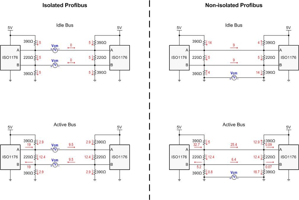
    below are simulations showing the current flows in idle and active mode for isolated and non-isolated Profibus links. I simulated up to 7V common-mode noise in the isolated mode and also 7V ground potential difference in the non-isolated mode.

    The worst case power consumption for the 390 W resistors is in Idle mode with (5mA)2 x 390 W = 10mW, and for the 220 W resistors in Active mode with (12.4mA)2 x 220 W = 34mW. I recommend using 1/16W ratings for all resistors and you'll be fine.

    Best regards, Thomas

  • Thomas, thanks for your kindly help.

    Yes, we planed to use the isolated mode, I did not take this into consideration, then I don't need to put so big resistors there.

     Regards,

    Linda