This thread has been locked.

If you have a related question, please click the "Ask a related question" button in the top right corner. The newly created question will be automatically linked to this question.

DP83869HM: DP83869HM: Fiber link does not come up with datasheet sequence unless register 0x1E is written

Part Number: DP83869HM

Hi TI Team,

QUESTION 1:

I am using DP83869HM in RGMII-to-1000BASE-X mode with an RFSoC board.

I followed the register configuration sequence exactly as described in the datasheet
DP83869HM (SNLS614D, Revised June 2025), section 7.4.8.2 "RGMII-to-1000Base-X Mode".


image.png

image.png

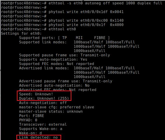
However, the fiber link cannot come up after following the official procedure.

I would like to understand why this is happening and identify any potential missing steps or requirements.

QUESTION 2:

The interesting part is that after additionally writing:

image.png

the link comes up immediately

image.png

According to the datasheet, register 0x1E is described as GEN_CFG4, and it does not appear to be a fiber-specific control register.

This makes me confused because the behavior suggests that register 0x1E is affecting fiber bring-up.

Could you explain why writing to Register 0x1E affects the fiber link-up process? Additionally, if the datasheet sequence is incomplete, what is the correct configuration or adjustment needed to ensure a reliable fiber link-up?

Thanks in advance

Rita

  • Hi Rita,

    Thanks for the query. Allow me to look at this closer today.

    Sincerely,

    Gerome

  • Hi Rita,

    I was able to evaluate this on my EVMs and don't see the reported behavior.

    1x EVM set to SGMII to Copper via bootstrap (DUT)

    1x EVM set to RGMII to Copper via bootstrap

    LED_0 shown as FX link. Initially off.

    As soon as Reg 0x1DF is set to 0x41, link was established. 0xC00 was already at 0x1140. No soft restart was initiated, but is encouraged in general.

    How is your system detecting link? With LED? With Register read of 0xC01?

    Sincerely,

    Gerome

  • Hi Gerome,

    This is a custom board using the DP83869HM PHY.
    The MAC is connected to the PHY via an RGMII interface.
    By default, the PHY is configured for RGMII to Copper (RJ45).
    The board also supports fiber connection via SFP, and the PHY mode is switched through MDIO register configuration.
    My goal is to switch the PHY from the default copper mode to fiber mode and verify actual link-up at the system level using ethtool.
    In my current setup, I am using an SFP loopback module for link verification.
    I followed the datasheet/application note procedure to configure the PHY for fiber mode via MDIO register settings.
    However, after applying the configuration, ethtool still does not report link up.


    My expectation is that once the PHY is correctly switched to fiber mode, link-up should be detectable at the MAC/system level (ethtool).
    Could you please confirm:
    1. Whether link-up via ethtool is expected after switching to fiber mode under this configuration?
    2. If any additional register settings or initialization steps are required beyond the documented procedure?

  • Hi Rita,

    While I am not a software expert, I would expect that ethtool would properly recognize linkup in this configuration.

    To my knowledge, I am not aware of any register settings as my configuration is identical to yours regrading bootstrapping. I would advise using register access to manually verify the PHY link up as I can see linkup on my side via LED.

    Sincerely,

    Gerome 

  • Hi Gerome,

    Understood. I’ll do some more testing on my side. Thank you for your help.

    Thanks again,

    Rita