TDES960: Schematic Check and Help

Part Number: TDES960
Other Parts Discussed in Thread: TSER953

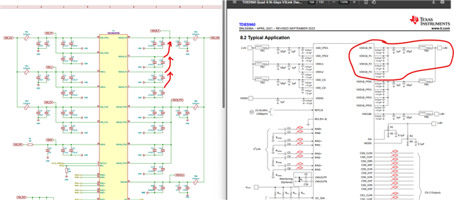
Hi, when we connect Arducam Tdes960 our device can detect it by I2C. When we connect our hardware TDES960_V1.0.pdf it does not detect I2C. All voltages are correct. And we have changed I2C 1.8V & connect 1.8to3.3V to PDB pin but could not detect device, 25MHZ ossilation can be seen with ossiloscope. Can any body help to us to fix? Thanks.Screenshot 2026-04-22 at 13.47.39.png

  • Hello Betul,

    Just to double-check, you connected to this Arducam board and everything worked fine, right?

    https://www.arducam.com/arducam-v3link-camera-kit-for-ti-development-boards.html

    But in your own custom design, you cannot communicate with the TDES960 device.

    ...

    I can take a look at the schematic and see if I notice anything.

    Best,

    Justin Phan

  • Hi Justin,

    Yes, that is correct. I have tested the Arducam V3Link kit you mentioned and it works perfectly—I am able to capture video streams without any issues.

    The problem only occurs with our custom board design where we cannot establish communication with the TDES960. I would appreciate it if you could review the schematic. I will share the relevant parts with you shortly.

    Best regards.

  • All voltage levels is as expected
    1.8V
    1.1V
    3.3V
    they all are perfect.

  • Hello Betul,

    Based on the schematic, it doesn't seem like the VDD18_P1/2/3 pins are connected to a 1.8V rail. I don't see a net name that ties them to a 1.8V rail.

    Best,

    Justin Phan

  • Hi Justin, I hope it is the reason let us try tomorrow and let you know, thanks for your attention:)

    It might be the reason you think?

  • Hello Betul,

    Yeah, that is what I think is the most likely cause. You can try to solder the a wire from the capacitor to the 1.8V rail. This will probably be a bit hard, depending on your layout. And this rework will cause some extra noise at the power pins, but hopefully you are still within the datasheet noise specification. It might be able to get the chip to power-up.

    Besides that, make sure the Power-Up Sequence can be followed.

    Best,

    Justin Phan

  • Thanks Justin, thanks for your help.

  • i2cdetect -y 4

         0  1  2  3  4  5  6  7  8  9  a  b  c  d  e  f

    00:                         -- -- -- -- -- -- -- -- 

    10: -- -- -- -- -- -- -- -- -- -- -- -- -- -- -- -- 

    20: -- -- -- -- -- -- -- -- -- -- -- -- -- -- -- -- 

    30: 30 -- -- -- -- -- -- -- -- -- -- -- -- -- -- -- 

    40: -- -- -- -- -- -- -- -- -- -- -- -- -- -- -- -- 

    50: -- -- -- -- -- -- -- -- -- -- -- -- -- -- -- -- 

    60: -- -- -- -- -- -- -- -- -- -- -- -- -- -- -- -- 

    70: -- -- -- -- -- -- -- --                         
    Now it detects I2C, we will keep working on it and let you know. Thanks for your help.

  • Sounds good. That is the right address, based on your IDX settings. You should be able to communicate.

  • Hi Justin, 

    Now when we try with Arducam board it shows 4 cameras like this.

    When we connect our board, it does not recognise cameras, cameras has 9V voltages. can you please check and give us some help. Thanks.

  • Hello Betul,

    Are you connecting your TDES960 board to a Raspberry Pi? And what cameras are you using? Do they have a TSER953 on them?

    Best,

    Justin Phan

  • Hi Justin

    We have our own custom board, yes we have 4 cameras, I am sending image to you from private messages, we gave 4 tser953 cameras, when we use Arducam TDES960 everything works perfectly with our own custom board it is Rockchip RK3566, we solved driver and device tree development, now we only need run our own tdes960, which I already send its design files to you at private messages, and we could not find any difference except you find :) thanks for your support.

  • Hello Betul,

    At the very least, you should be able to detect the TSER953 serializer at power-up. Once you power-up the TDES960 board, you should be powering the TSER953 and the image sensor through PoC. The I2C address of the TSER953 should be visible from the TDES960 I2C bus if everything is powered-up correctly.

    Some debug steps:

    1) Do you know what MODE setting is on the TSER953? This is determined by the voltage divider network on the TSER953 MODE pin. The MODE setting on the TSER953 and the TDES960 need to match, in order to get LOCK at power-up.

    2) If you set 960 reg 0x4C = 0x01, you are looking at the RX Port 0 registers on theTDES960. Make sure that the camera module is connected to RX Port 0. Then, read registers 0x5B and 0x5C on the TDES960.

    If your TDES960 and TSER953 are properly powered-up and LOCKed, then the SER_ID should be populated with the I2C address of the connected serializer.

    Best,

    Justin Phan

  • Hi Justing,

    We are able to run Arducam TDES960 + 4 x Arducam TSER953 + IMX219 with our main board. Like bottom picture, we can even get video perfect it works like a charm. I already sent its picture to you through private message.

    Now our custom design TDES960 can be detected through I2C. But when we connect 4 x Arducam TSER953 + IMX219 cameras like we connect to Arducam TDES960 board, we cannot detect cameras, this point we asked you to solve it. 

    For next steps we will test our custom TSER953 board too, if we pass this step. 

    Thanks...

  • By the way this is our 
    MODE& IDx Selection

  • Hi Justin, 
    I want to ask one more question.

    If our layout has problems, would it prevent the TSER953 from achieving a LOCK entirely, or would it only cause MIPI errors?

    For instance, if our AC coupling capacitors are incorrectly placed near the connectors instead of near the IC pins, could this be the reason for the LOCK failure?

    I am asking this because we can successfully communicate with the TDES960 over I2C.

    Given that the physical connection between the TDES960 and TSER953 is minimal, and the only major difference between our design and the datasheet is the AC coupling capacitor placement, I am wondering if this specific issue is preventing the LOCK.

    Thanks...

    Edit:

    When I check also Arducam TDES960 AC coupling capacitors are far IC to, not near them Disappointed

    I have no idea how to find problems, thanks.

  • Hi Justin, we checked over and over again schematic, and we could not find any problems, we are waiting your suggestions.

    Thanks...

  • Hello Betul,

    By the way this is our 
    MODE& IDx Selection

    Yes, I saw this. I am asking you to confirm the IDX and MODE settings on the TSER953 serializers. To make sure that the MODE settings on the SER and DES match.

    If our layout has problems, would it prevent the TSER953 from achieving a LOCK entirely, or would it only cause MIPI errors?

    Yes, if your layout has issues, it can cause connection issues. Our SerDes devices have Insertion Loss and Return Loss limits. Your layout needs to follow strict high-speed layout guidelines, in order to make sure that the SerDes devices can LOCK onto each other. If the serializer cannot be detected, then one possible cause is that there is too much loss on the high-speed channel, which means the SerDes devices cannot LOCK onto each other.

    As a first step, I am asking you to read the diagnostics registers in the TDES960, so we can narrow down root cause.

    2) If you set 960 reg 0x4C = 0x01, you are looking at the RX Port 0 registers on theTDES960. Make sure that the camera module is connected to RX Port 0. Then, read registers 0x5B and 0x5C on the TDES960.

    Have you done this?

    ...

    Have you simulated or measured Insertion Loss or Return Loss in your system?

    And what cable are you using in your system?

    ...

    I can take a look at your layout to help you check if the PCB layout has major issues, but I am having some computer issues at the moment. I see you shared KiCad layout files. Can you export as Gerber files and share those instead?

    Best,

    Justin Phan

  • Hi Justin we find problem, it is about connector, we were using different connector, and it is very sensitive, now we will produce with Fakra Connector again, thanks for your help, we will test and get back to you 4-5 weeks later Slight smile