This thread has been locked.

If you have a related question, please click the "Ask a related question" button in the top right corner. The newly created question will be automatically linked to this question.

TXE8116: Behavior when 32-bit data is received by a 24-bit register device with CS asserted

Part Number: TXE8116
Other Parts Discussed in Thread: TXE8124,

Hi team,
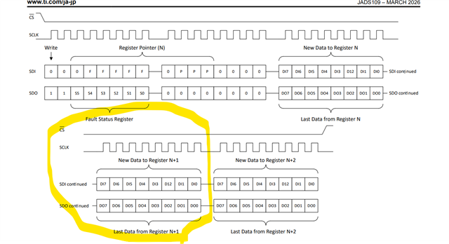
This IC has a 24-bit register. When CS is asserted, if 32-bit data is transmitted to the device, how will it behave?
Specifically:
  • Will the latter 8 bits be ignored, and only the first 24 bits be latched as valid data?
  • Is this kind of operation (sending 32 bits to a 24-bit register) acceptable and free of issues from a specification and reliability standpoint?
Best Regards,
Shota
  • Hello Shota-san,

    Since the device only accepts a 24-bit frame per CS de-assertion, sending a 32-bit frame can potentially corrupt the original data.

    Most SPI controllers typically send 8-bit or 16-bit transfers. One recommendation is to send three 8-bit transfers with CS held low across all three.

    Regards,

    Josh

  • Hi Josh-san,
    Thank you for reply.
    Let me ask one more question.
    As described here, the SDI data length is required to be [16 + (N × 8)] bits.

    In actual communication, however, it seems that only 24-bit SDI data is supported.
    In this case
    • Is N limited to only N = 1, meaning that only 24-bit SDI communication is possible?
    • If so, could you please explain the reason why the specification is written in a generalized form such as [16 + (N × 8)] bits instead of simply stating 24 bits?
    I would like to better understand the design intent and whether values of N other than 1 are practically supported.
    Best Regards,
    Shota
  • Hello Shota-san,

    There was a recent datasheet revision where some of the wording was revised. Please take a look at TXE8124 datasheet.

    Section 7.5.2 states that N = 1 signifies a single transfer, while N >1 enables burst mode. For example, sending 32 bits (e.g., 0x0300FFFF) causes the auto-incrementing register pointer to load the final byte into the subsequent address. In this case, the first 24 bits configure Port 0 to logic high, while the final 8 bits configure Port 1 to logic high.

    Hope this helps!

    Regards,

    Josh

  • Hi Josh-san,
    Thank you for reply.
    I would like to confirm my understanding of the bit/byte mapping shown in the figure.
    • In this diagram, is the “last 8 bits” corresponding to the yellow circled area?

    In addition, for the 32-bit access in burst mode:
    • After the initial 24 bits are written, is the following byte automatically written as the third byte of the next port?

    • Does the same automatic byte-to-next-port behavior also apply during read operations?
    I would appreciate your confirmation on how the device internally handles byte alignment and port incrementing in burst mode for both write and read transactions.
    Thank you for your patience and continued support while I asked several questions. Your help is greatly appreciated.
    Best Regards,
    Shota
  • Hi Josh-san,
    I have one more question regarding the port write operation.
    1. If we write to Port 1 from the beginning, do we configure the final 8 bits as logic high for Port 2?
      For example, in the case of a 32-bit write such as 0x0310FFFF.
    2. For TXE8116, which only has ports up to Port 1, if we write to Port 1 from the beginning, do we configure the final 8 bits as logic high for Port 0?
    I would like to confirm the correct bit configuration behavior in these cases.
    Best Regards,
    Shota
  • Hello Shota-san,

    1) In this diagram, is the “last 8 bits” corresponding to the yellow circled area?

    • Yes that's correct. The last 8 bits that I'm referring corresponds to the yellow circled area.

    2) After the initial 24 bits are written, is the following byte automatically written as the third byte of the next port?

    • In the diagram you showed, the next byte would technically be the fourth byte since 24-bits only contain 3 bytes. But to answer your question, yes once the initial 24 bits are written the next byte will automatically be written to the next port selection

    3) Does the same automatic byte-to-next-port behavior also apply during read operations?

    • Yes it does. Please look at Figure 7-10

    4) If we write to Port 1 from the beginning, do we configure the final 8 bits as logic high for Port 2? For example, in the case of a 32-bit write such as 0x0310FFFF.

    • Are you planning to use Port 2? If not, I would configure the final 8 bits as logic low. This way you can minimize the supply current on this part

    5) For TXE8116, which only has ports up to Port 1, if we write to Port 1 from the beginning, do we configure the final 8 bits as logic high for Port 0?

    • Once the register pointer is not able to increase automatically (for example you have 8 bits left after written to Port 1), any data that follows will be ignored. See section 7.5.3 or image below

    Regards,

    Josh

  • Hi Josh-san,
    Thank you for your reply. I understand.
    I would like to confirm my understanding of the TXE8116 write operation behavior.
    If Port1 is selected from the beginning and a 32-bit write operation is performed, can we assume that the last 8 bits are ignored and the device correctly recognizes only the first 24 bits as valid data?
    In other words, is it guaranteed that writing 32 bits to Port1 will effectively be handled as a 24-bit write, with the upper (or remaining) 8 bits being discarded without causing any issues?
    Best Regards,
    Shota
  • Hey Shota-san,

    Josh is currently out of office, and responses will be delayed. Thanks for your patience on this one.

    Regards,

    Jack

  • Hello Shota-san,

    Your understanding is correct. The last 8 bits (when writing a 32-bit operation to Port 1) will be ignored without causing any issues.

    Regards,

    Josh